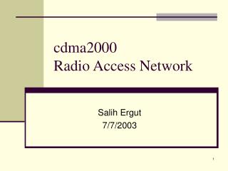
CDMA System Configuration !
CDMA System Configuration !. System Architecture. MSC. EIR. IWF. E. F. L. Abis. B. A. MS. BTS. BSC. MSC. VLR. Um. G. Q. C. D. SC. M. SC. HLR. VLR. H. M. PDSN. ESME. AUC. WIN/VMS. A REAL CDMA system. MSC. BSC. BTS. System Architecture. BSS configuration.

CDMA System Configuration !
E N D
Presentation Transcript
System Architecture MSC EIR IWF E F L Abis B A MS BTS BSC MSC VLR Um G Q C D SC M SC HLR VLR H M PDSN ESME AUC WIN/VMS
A REAL CDMA system MSC BSC BTS
BSS configuration • BTS configuration • BSC/PCF configuration • PDSN configuration
BTS configuration preparation • Um loss(GOS) • Traffic per sub • Soft handoff rate • Antennae Channels on the BTS
BTS calculation BTS Qty. Traffic per sub Total capacity Total Traffic Traffic per BTS SCT Qty. Traffic per SCT Channels Per sector Erl Table B Traffic per BTS Divided by sector Qty.
Capacity adjust • Because of the data service has influence on the voice capacity • Manual adjust
Antenna Choosing • Omni • Sector • Single Polarization • Dual Polarization • Antenna Gain
PCF PDSN • Ratio of data user • Calculation module • Total traffic • Calculation of “Qty. Of BSC Data Element(SDE)(actived PPP)”
IWF • Ratio of circuit data user • Total traffic • Calculation of “Qty. Of BSC Circuit Data Element”
BSS configuration Summary • Traffic • GOS • Erl B table • Voice Channel • Data Channel “Qty. Of BSC Data Element(SDE)(active PPP)” • Circuit data Channel ”Qty. Of BSC Circuit Data Element”
MSS configuration • MSC • HLR • SC
MSC configuration • Key points • Should we co-locate the MSC & HLR • Save a SS7 transfer Rack • Capacity of MSC/HLR • Traffic per sub • SS7 links calculation
MSC & HLR MSC HLR SS7 To IP IP Ethernet SS7 links (E1)
SS7 calculation • Signaling over A interface • Signaling to HLR • Signaling to PSTN • Signaling to other MSC • Signaling to SC • Signaling to VMS • ……… Headache
PDSN,SC • Total Qty. of sub supported • Traffic
Other configuration • WIN • VMS • Transmission/Microwave • Power system • DDF
Real Picture of BSC • HIRS: 高速互联路由子系统 • NCM: 网络控制板 • NIM: 网络接口板 • CDSU:信道数据服务单元 • CPS: 呼叫处理子系统 • CPM: 呼叫处理模块 • TS:时钟子系统 • TCM:时钟控制模块 • GPSTM:GPS/GLONASS接收模块 • SVBS:声码器/选择器子系统 • SVM:声码器/选择器模块 • SVICM:声码器/选择器控制模块 • PCFS:分组数据业务子系统 • PCF:分组数据业务模块 • PCFIM:分组数据业务接口控制模块
SVBS • Codec for QCELP,EVRC and 64kb/s PCM • CDMA system power control functions • Signaling interface between MSC and BSC(SS7) • Selector Selector : process the routines of Handoff/Handover CODEC SVBS 8K EVRC Wireless 64K PCM Wireless
SVBS • One SVM can handle 15 channels • One SVBS sub-system can handle 120 channels • One ESVIM can handle 6 IWF channels • One SVBS rack can hold 10 SVBS sub-system • One BSC can support 6 SVBS racks
CDSU • 192 channels per 1 E1. • Based on Packet data mode BSC BTS CDSU Abis Non-channelized E1 CDSU CDSU SDH PDH Satellite MicroWave …. CDSU CDSU
CDSU Abis Based On CDSU • Data communication between BTS and BSC • Using normal E1 • Daisy chain networking E1 E1 BTS BTS BTS To BSC
BTS Data flow Remote RF Subsystem Local RF Subsystem TRXs TRXs HPAs/LPAs HPAs/LPAs RFEs RFEs GPS GPS + GPS GPS + Glonass Glonass GPS* BTS Baseband Subsystem CEs Cable BTS Fiber
ZXC10-BTS 1x80基站收发信机机架结构 • RFS:射频子系统 • RFE: 射频前端 • HPA: 高功放 • TRX: 收发信机 • TFS:时钟频率子系统 • GPS • TCM • FDM • BDS:基带调制解调子系统 • RFIM: 射频接口模块 • CHM32/64: 1x信道板 • CCM: 通信控制板 • CDSU:信道数据服务单元
Sector Antenna • 20、30、65、90、105、120、180
Antenna choose 1 20、30 (normally with high gain)for narrow belt areas and highways 65 :for density urban city. Standard antenna 90 :for suburb areas 105: for low traffic areas, like mountain areas with vast coverage needs 120、180 : for some very wide angle coverage. Seldom use.
Antenna choose 2 • Antenna Gain • Higher gain, longer shooting range • Less gain , larger coverage near antenna • Polarity • Dual polarized antennas are easy to be with higher gains • Dual polarized antennas are easier to install
Antenna Gain • Normal Gain Higher Gain Lower Gain Antenna Antenna Antenna
Polarity Relative position has to be carefully adjusted Antenna Antenna • Single polarity antenna work in pairs. Engineering is very hard to do • Dual polarity antenna work with one enough. Engineering is very easy. • Omni antenna is single polarity only Antenna Single polarity antenna Dual polarity antenna
PART II How to do configuration • BSC • SVM/PCF Capacity • CDSU How many base stations • BTS • CHM Capacity • RF Module Carriers/Sectors
PART II How to do configuration • International market is special • Making configuration is difficult then domestic market Estimate BSC: 5040Erl,7200 BTS: 4 carriers/ 3 sections. 0~50 channel per section