Download
1 / 8
80 likes | 279 Views
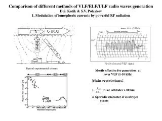
Mostly effective for generation at lover VLF (1-10 kHz). Main restrictions : at altitudes > 80 km 2. Sporadic character of electrojet events. Comparison of different methods of VLF/ELF/ULF radio waves generation D.S. Kotik & S.V. Polaykov

E N D
Mostly effective for generation at lover VLF (1-10 kHz) • Main restrictions: • at altitudes > 80 km • 2. Sporadic character of electrojet events Comparison of different methods of VLF/ELF/ULF radio waves generation D.S. Kotik & S.V. Polaykov 1. Modulation of ionospheric currents by powerful RF radiation Firstly detected VLF signal Typical experimental scheme Summary of Tromsǿ results
2. Moving ionospheric source. (-) (+) x h~80km e –i (ωt+/-Ώ)t e -iωt H1 H2 d1=100(200)m op1 op2 R1=30km R2=300km
3. VLF Production by HF Heating Using the Thermal Cubic Nonlinearity h~80km e –i (2ωt+/-Ώ)t e -iωt H1 H2 d1=100m op1 R1=30km Nonlinear nonresomance current: em 01.19.1990 f1=4.63 MHz P1=250 kW f2=9.05 MHz P2 =500 kW X polarization O polarization The magnification factor is -- Comparison with electrojet modulation method gives by ratio
4. ELF generation using 1 MWt broadcasting stations. Lovo. R=1300km S. Petersburg ● Moscow N. Novgorod An example of correlation of signal amplitude received at NN with magnetic field variations on the Apatity for case KP-5+ The case of week disturbance (KP=20)
To Barentsburg, 1200km 5. ULF generation using power lines Geometry of the experiment AverageULF spectrum for HN-S Hautavaara, 00:03-03:00 LT, 28.09.01. Sodankyla data (distance 500 km) HE-W component. Lovozero
5. EXPERIMENTAL INSTALLATIONS Consumers Power line 108 km long Power plant ~380kV δ CONTROLLER R Matching capacitors power ~380V 50Hz ULF generator- converter Precision generator For F = 10 Hz δ ~ 6-8 km
BAND METHOD APPLIANCE FIELDS 7. CONCLUSIONS Low VLF 1 –10 kHz Direct modulation of ionospheric currents by RF heaters Diagnostic of low Ionosphere, studying of propagation in E-I waveguide High VLF 10 –20 kHz 1. Moving source, 2. Thermal cubic nonlinearity. Both using heaters with complicate arrays Diagnostic of low Ionosphere, studying of E-I waveguide, injection into magnetosphere ELF 0.1 – 1 kHz Direct modulation of ionospheric currents by powerful broadcasting stations Diagnostic of low Ionosphere, studying of E-I waveguide, Earth exploration for geoengineering ULF below 100Hz Long power lines with ULF generator Diagnostic of low Ionosphere, studying of E-I waveguide, Deep Earth exploration Studying of near Earth ULF resonators injection into magnetosphere Magnetic field distance dependence for Kola ground based ULF facility (for three azimuth directions) and for SURA and Tromso ionospheric ULF antennas at 40 Hz radiated frequency.
The estimated and experimentally confirmed zone of assured ULF signal detection for ULFRAD. The ULFRAD concept