Download
1 / 31
310 likes | 522 Views
Electronic Troubleshooting. Chapter 11 Digital Systems. Digital Systems. Key Aspects Analyzing large systems based upon info in system diagrams Topics covered Understanding Digital Systems Bus-oriented Systems Problems in digital systems Troubleshooting Digital Systems

E N D
Electronic Troubleshooting Chapter 11 Digital Systems
Digital Systems • Key Aspects • Analyzing large systems based upon info in system diagrams • Topics covered • Understanding Digital Systems • Bus-oriented Systems • Problems in digital systems • Troubleshooting Digital Systems • Testing and Troubleshooting Microprocessor systems
Understanding Digital Systems • Key Aspects • Most digital and computer (microprocessor or micro-controller) controlled systems can be represented by a block diagram similar to the one on the right
Understanding Digital Systems • Example System • Simple Interval Counter • Control subsystem: • Control Flip-Flop • Clock • NAND Gate –regulates control signals • Input Subsystem • Reset, Start, & Stop switches • Arithmetic Subsystem • Tree 7490’s arranged in a multistage counter
Understanding Digital Systems • Example System • Simple Interval Counter • Output • 7-Segement displays , drivers , and input signals • Memory • Lacks this subsystem • Testing notes • If the subsystem inputs and outputs are known • Subsystems operation testable using I/O values
Bus-oriented Systems • Characteristics • Bus Symbols on diagrams • Arrow with a diagonal line and the number of connected lines • Replaced 7 lines between the 7447 IC and the 7-Seg display • Busses structures require multiple devices to use circuits (lines) in a bus as Inputs & Outputs • Can cause significant problems • Example: Gate 1 tries to pull point X to a logic 1 and Gate 2 tries to put it at a logic 0 – Indeterminate result
Bus-oriented Systems • Characteristics • Replace the gates driving lines of a Bus with gates that use external pull-up resistors • Example 7401 NAND Gates w/external pull-up resistors • The previous using these types of gates resolves to the gate putting out a logic 0 controls the line
Bus-oriented Systems • Bus Example • Both “X” and “W” inputs drive the lines of th bus • 4-bit data bus • Lines b0 – bf • Drives multiple gated outputs • “Y” & “Z”
Bus-oriented Systems • Tristate Outputs • Better solution • Has the faster rise time of the Totem Pole outputs • Has 3 states : High, Low, High Impedance • Operation • The added diode D1 will ground out the collector of Q2 and the base of Q3 • Q2 and Q3 are off • No current through R3 and Q4 is off • Equivalent Circuit – lower left
Bus-oriented Systems • Tristate Outputs • Example Circuit
Bus-oriented Systems • Address Bus • Used to select ICs , memory locations, multi-line Tristate inverters or buffers (same as inverters but no inversion of levels), etc • Three binary address lines select one of eight outputs • A way to select a bank of tristes to activate
Bus-oriented Systems • Address Decoder circuit • Three lines on a 8-bit address bus is used to activate one of up-to eight banks of tristates • Controlling the writing data to another Bus • Typical circuit in Bus based systems • Microcomputers, micro-controllors, etc
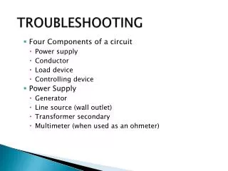
Problems in digital systems • Typical Problems covered • Ringing and Reflections • Power Supply Glitches • Changes in Layout, Components, and Temperature • Ringing and Reflections
Problems in digital systems • Ringing and Reflections • Caused by long interconnecting lines • As the interconnection lines length becomes significant to the wavelength or the signal frequency • Load, source and transmission line impedance mismatch can lead to signal reflections and distortions • Reflected waves interfere with new signals on the same line • May be in or out of phase with the new signal • End Result: the refection combines with the signal forming a new third signal.
Problems in digital systems • Ringing and Reflections • Distortion call also occur on long interconnecting lines due to the different impedances seen by different components of the square wave placed on the lines • All interconnecting lines have distributed capacitance and inductances • The longer the lines the more the significant the distributed components • Square waves have been analyzed as consisting of a large collection of signals with a large range of frequencies with differing amplitudes • They react to long transmission line according to that analysis
Problems in digital systems • Ringing and Reflections • Square waves have been analyzed - continued • Higher frequency component waveforms suffer more attenuation than lower frequency waveforms • Thus more distortion • Noise pick-up and crosstalk • Longer lines form better antennas to pick-up external signals/noise • Longer lines form better antennas to pick-up internal signals from nearby lines caring other signals - aka Crosstalk
Problems in digital systems See Example Problem 11-1 on page 320 • Power Supply Glitches • Sudden changes in current draw by one of several components in a parallel connection to a regulated power supply can cause a voltage glitch • Caused by the voltage developed across the distributed inductance of the line supplying the power • Very short duration – only as long as the current draw is changing • Voltage spike per the following:
Problems in digital systems • Power Supply Glitches • Solution Below:
Problems in digital systems • Ground Plane caused problems • A large shared ground plane (as shown in the previous examples) • Large current draws can lead to ground level fluctuations and related problems • Best cure is at design time • Provide each part of the circuit it’s own path to ground • Thus minimizing the sharing of problems • See Figure 11-14 on page 321
Troubleshooting Digital Systems • Same steps as for an analog system • Understand the circuit operation • Apply typical inputs • Successively split the system into smaller and smaller sections. • Look for circuits that have good inputs and abnormal outputs • Start at the approximate middle between inputs and outputs • Sample circuit is analyzed • A frequency Counter
Troubleshooting Digital Systems Pages 324 and 325 • Same steps as for an analog system • A frequency Counter
Troubleshooting Digital Systems • Same steps as for an analog system • Sample circuit is analyzed • How it works (see page 325) • Signal to be measure is feed into the Squaring Block • TTL compatible square wave comes out • Before the start of a measurement – the control circuit resets all the counters • Then the squared input signal goes through the gate for 1 second COUNT-NOT pulses • At the freq of the input • COUNT-NOT pulses are feed to the counters for 1 second • Gate is disabled to stop the counting after one second • Counters hold the count of the number of input pulses that occurred during the 1-second measurement period
Troubleshooting Digital Systems • Same steps as for an analog system • Sample circuit is analyzed • How it works (see page 325) • Then a store pulse is feed the Latches – enabling the storage of the count that was on the output pins of the counters • The latches feed the BCD to 7-Segement drivers which drive the displays • The clock is a 555 chip and the output from pin 3 is a rectangular waveform that has a pulse width of 1 second • Calibrated by adjusting pot R1 • The falling edge of the Clock (555 chip -pin 3 ) triggers the one-shot output from pin 13 of chip 74221 • 100µsec pulse – set by R3-C2 • Enables the latches to read the output pins of the counters
Troubleshooting Digital Systems • Same steps as for an analog system • Sample circuit is analyzed • How it works (see page 325) • The falling edge of the Latch enable one-shot pulse enables another one-shot output from 74221 – pin 5 • Pulse resets the counters • The count of pulses stored in the latches represents the frequency of the input signal – since they only count during the one second measurement period • Timing diagram on page 327 of the textbook • Troubleshooting the sample circuit • Inject a testing signal of a few hundred Hz • Watch the displays • Normal operation is obvious
Troubleshooting Digital Systems • Same steps as for an analog system • Troubleshooting the sample circuit • Watch the displays • Indications of the source of abnormal operation can also be discerned from the displays. • If the least significant digit is operating correctly and the second and third aren’t • All the Input, timing & control circuitry is working, also IC’s 7, 10, and 13 must also be functional - check the IC supporting the other displays • If none of the displays are functioning normally • Go to the middle of the circuit. Check the outputs of IC 7 • If good split the remaining part of the circuit and test again. etc • Troubleshooting flow chart on page 328 • Large scale Integrated IC version on page 331
Testing and Troubleshooting Microprocessor systems • Very common to find microprocessors, microcontrollers, Programmable Logic devices in circuits • Designs that can be varied to meet a situation by changing the program in the device • i.e., first circuit that input buttons on a WMS Bluebird Slot Machine is a PIC microcontroller • Programmed to de-bounce input button activations • Some items can be checked even without a complete understanding of such a system.
Testing and Troubleshooting Microprocessor systems • First Step –understand the system • Sample system - MC6800 Microprocessor single board system - See Figure 11-25 on page 333
Testing and Troubleshooting Microprocessor systems • First Step –understand the system • Sample System - MC6800 – continued • Has all the subsystems shown in Figure 11-1 on page 309 • MC6800 chip contains the control and arithmetic functions • 74LS244 chip contains the Input circuits • Tristate octal input buffer • Connects external inputs to the data bus when enabled • Pins 1G and 2G are active Low • Output data leaves through the octal buffer 74LS373 • 2716 is EPROM that holds the system program(s) • 8 data bits
Testing and Troubleshooting Microprocessor systems • First Step –understand the system • Sample System - MC6800 – continued • RAM - two 2112 ICs • 4 data bits • Need two for a byte of data • Chip Select Circuit • 74LS155 – 4 to 1 decoder • 2- address lines are used to select one of four ICs (A15 and A12) • A12 = 0 and A15 = 1 selects output 2Y2 • A12 = 0 and A15 = 0 selects output 2Y0
Testing and Troubleshooting Microprocessor systems • Simple tests w/out maintenance programming and special test equipment • Usually the major components are in sockets and can be removed • Remove them an test surface mounted circuits that are isolated • On the sample circuit the MPU, RAM and EPROM can be removed • Obvious circuit to test is the clock • On Sample: Pins 01 and 02 of the MC6875 and MC6800 chips • Next check the Chip select circuits • set MC6800 address pins A12 & A15 and check CE-NOT pins on the other chips
Testing and Troubleshooting Microprocessor systems • Simple tests w/out –continued • Major components – removed - continued • Check the input buffers by using external data settings and the appropriate address settings for A12 & A15 • Read the inputted data at the data lines for any of the removed ICs • Continue with all the supporting circuits that can be directly tested. • Any inverters and gates can be tested using a logic probe and digital pulser • Retest with some or all the major components in place