Download
1 / 48
500 likes | 751 Views
Electronic Troubleshooting ET198B Chapter 2. Most electronic device need: - DC (Direct-Current) power - Batteries are one source: - They can become very costly - Due to replacement costs and labor - Better Source – DC Power Supply

E N D
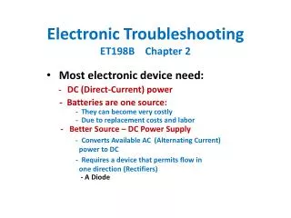
Electronic TroubleshootingET198B Chapter 2 Most electronic device need: - DC (Direct-Current) power - Batteries are one source: - They can become very costly - Due to replacement costs and labor - Better Source – DC Power Supply - Converts Available AC (Alternating Current) power to DC - Requires a device that permits flow in one direction (Rectifiers) - A Diode
Solid State Diode • When the P material is sufficiently positive with respect to the N material current flows • With Reverse polarity Current doesn’t flow
Diode Packages • Part numbers usually start as 1N as in 1N4001 • Many types of cases are possible • Range from glass to stud mountable metal cases • (for heat dissipation)
Characteristic Curve • In the flat region • When VF is between Breakdown and 0.7 V (forward bias voltage) for silicon based diodes almost no current flows • When VF is between Breakdown and 0.3 V (forward bias voltage) for germanium based diodes almost no current flows • Region to the right • When VF is higher than the forward bias voltage current increases rapidly for a slight voltage increase
Characteristic Curve • Region to the left • When VR is less than the Breakdown voltage current increases rapidly for a slight voltage decrease and the diode is destroyed • Except for tunnel and Zener diodes which are designed to operate in that region • Diodes designed as rectifiers are destroyed when operated in this region • Rectifying diodes come with a range of Breakdown voltages • 25V to thousands of volts • Always use ones with Breakdown voltages greater than any reverse voltage • Calculated based upon instantaneous voltages not RMS values (peak-to-peak voltages)
Measuring Diode Characteristics • For the drawings on the previous page • E = 6VDC and R=10Ω • Find VF and VR • An ideal diode • For a real diode with a breakdown voltage (VB) of 50VDC Half-wave Rectifier • Sample circuit in Fig A • Voltages taken at points “X” and “Y” with respect to Ground • O-scope not a meter
Half-wave Rectifier • Input Voltage 24 VP-P at “X” • Output Voltage at “Y” • Only the Positive ½ cycle of the input reaches the output • Is the Diode a real one or ideal? • How can you tell? • Calculation Notes: • Usually ignore the diode VF if the voltages involved are 10 times larger than VF • Except on Tests and quizzes in this course
Filter Capacitors • Used to smooth the pulses from a rectifier Circuit • On the first pulse seen by the capacitor • It’s voltage closely matches the rising input voltage • After the input voltage reaches its peak value the current to the load resistor is supplied from the capacitor • The output voltage or VY slowly decreases • The rate of decrease is dependent upon the value of R times C - the Time Constant (τ)
Filter Capacitors • Used to smooth the pulses from a rectifier Circuit • On the first pulse seen by the capacitor • The output voltage or VY slowly decreases • This RC time constant (τ) should be long compared to the time between pulses • The output voltage decreases per the equation after reaching its peek voltage. t= elapsed time, VP = max VO • The voltage decreases until the next pulse is higher than the output voltage • On the second and following pulses • The process repeats per the previous sketch • The Cap is charged during the positive going transition of the pulse • The cap supplies the current at other times
Filter Capacitors • Used to smooth the pulses from a rectifier Circuit • On the second and following pulses • Key aspects of the resulting output voltage • It still has pulses, but they are smaller than before the Cap • The pulses alternate plus and minus around an average output voltage (Vave) • The peak to peak value of the alterations is known as the ripple voltage (Vrip) • Calculating Vrip , where: • I = Load current in Amps • T = time between recharging pulses • C = filter capacitance in farads • Calculating VAVE , where
Effects of Load Current & Filter Capacitance • Anything that makes the RC time constant smaller increases the ripple voltage (Vrip) • A decreased RL causes increased current and more Vrip • A change to a lower value of capacitance causes a smaller τ and more Vrip
Effects of Load Current & Filter Capacitance • Anything that makes the RC time constant smaller increases the ripple voltage (Vrip) • Decreased RC time constant (τ) can be caused by: • Improper replacement parts Installed during a repair • Change in the value of the filter capacitor with age – especially with electrolytic Caps
Effects of Load Current & Filter Capacitance • Example Problem: • Ideal Diode, VP = 15V, ILoad= 20 mA, Freq=60Hz, C = 200µF • Find: Vrip , Vave • Practice. Repeat with: • Ideal Diode, VP(source) = 30V, ILoad= 25 mA, 60Hz source, C = 250µF • Repeat both for a silicon diode that has VF = 0.7v
Transformers • In power supplies • Used to step-up/down VP to a desired value based upon the required DC output voltage • Construction • The core is usually laminated sheets of iron or steel • Minimizes losses due to eddy currents • At least two windings of insulated wires (Fig B)
Transformers • Electrical characteristics • Voltages on the secondary and Primary Windings are related by the following equation: • Vsec = transformer secondary output voltage • Vpri = transformer primary (line) voltage • Nsec = number of wire turns on the secondary winding • Npri = number of wire turns on the primary winding NOTE: The formula will work for Vrms , VP , or VP-P • Usually specified by primary & secondary voltages in Vrms
Complete Halfwave Power Supply • All the discussed components plus: • Power cord, fuse, indicator lamp, and a switch • Questions • Transformer turns ratio (Nsec / Npri) • VP
Reverse Voltage • It is equal to the sum of the voltage on the Cap and the VP from the next ½ cycle of the input waveform • In other words the A simple rule for VB rating on a Diode is that it must exceed the VP-P of the transformer's secondary voltage
Reverse Voltage • Given 12 Vrms on the secondary • 16.97VP~ 17.0VP or Approx 34VP-P • Thus on the positive ½ cycle the Cap is charged to 16.3V • On the negative ½ cycle the anode side of the diode reaches – 17V • About 33.3 V ~ 34V across the diode
Full-wave Rectifier • Characteristics • For given components it will have twice the pulse rate on the output. • In a power supply it will have ½ the ripple voltage • Recharges the capacitor twice every input cycle • For a given output voltage the total secondary voltage will be double that of a ½ wave rectifier • Like a ½ wave - reversing the diode connections will result in negative pulses on the output • Circuit function • On half the input cycle • Point A is driven positive with respect to point B and the center tap of the transformer which is at ground
Full-wave Rectifier • Circuit function • On half the input cycle • Causes diode D1 to conduct and D2 is back biased and not conducting • Current flows through RL and D1 • On the next ½ cycle of the input • Point B is driven positive with respect to point A and the center tap of the transformer which is at ground • Causes diode D2 to conduct and D1 is back biased and not conducting • Current flows through RL and D2 • On both ½ cycles • Current through RL flows in the same direction
Full-wave Rectifier • Circuit function • Filter Capacitors • Need to smooth out the pulsating output to a DC voltage • For the same load , output voltage , and acceptable ripple voltage – the capacitor can be ½ the farad value • Same equation for Vrip and Vave work but the the period is ½ since there are two pulses per input cycle
Rectifier Assemblies • Full-wave Rectifier diode assemblies are available • Come packaged for • either positive or negative • outputs
Full-wave Rectifier • Example Problems • With the given circuit: • Vpri = 120VRMS @ 60 Hz, Vsec =20V • Find: VP, and PRV • For C= 250 μF, ILoad = 30 mA • Find: Vrip and the freq of the ripple voltage
Full-wave Rectifier • Example Problems • Find: VP, and PRV • VP=VC-Peek = 10V x 1.414 – 0.7V = 14.14- 0.7V = 13.44V • PRV ~ 13.44V – (-14.14V) = 27.58V ~ 2x VC-Peek~ 2xVDC • Find: Vrip and the freq of the ripple voltage • 60Hz => Period of 1/60 = 16.67mS • However T = 8.33 mS since it’s a Full-wave • Vrip freq = 1/T = 120Hz
Full-wave Rectifier • Example Problems • Find: The freq of the ripple voltage • 60Hz source and a ½ Wave Rectifier • 60Hz source and a Full Wave Rectifier • 400 Hz source and a Full Wave Rectifier • 800 Hz source and a ½ Wave Rectifier
Bridge Rectifier • Characteristics • Doesn’t need a center tapped transformer • Uses four diodes connected in a bridge circuit • Circuit function • When top of transformer is positive with respect to the bottom • D2 and D3 are forward biased and conduct • When the polarity is reversed • D1 and D4 are forward biased and conduct • Current flows through RL in the same direction regardless of polarity • PRV equals approximately the voltage across RL
Complete Full-wave Power Supply • Also needs a filter capacitor • VO without a load equals VP-Sec after accounting for the forward bias voltages of two diodes that are between the load and the transformer leads. • The VF for both diodes are usually ignored for VO of 15V or higher except for quizzes and tests in this course
Complete Full-wave Power Supply • Problems • Example • Vsec = 20 Vrms , IL =100mA • C=400µF • Find: VO , Vrip , and PRV • In Class Exercise • Problems 2-11 and 2-12 on pages 23 and 24
Complete Full-wave Power Supply Walk through assuming 6VP on the transformer secondary
Voltage Doubler Circuits • Full-wave Voltage Doubler • Produces VO that is twice as large as VP on the secondary terminals of the transformer. Freq of Vrip is twice input Freq. • Circuit Operation • When top of transformer is positive, D1 conducts and charges C1 to VP with the polarity shown • When Bottom of transformer is positive, D2 conducts and charges C2 to VP with the polarity shown • The voltage across the resistor is approx 2 x VP
Voltage Doubler Circuits • Half-wave Voltage Doubler • Produces VO that is twice as large as VP on the secondary terminals of the transformer. Freq of Vrip is equals input Freq • Circuit Operation • When bottom of transformer is positive, D1 conducts and charges C1 to VP with the polarity shown • When Top of transformer is positive, D2 conducts and charges C2 to VP + VC1 (approx 2 VP) with the polarity shown • The voltage across the resistor is approx 2 x VP
Power Supply Component Failures • Overview • Each component’s typical failures and testing methods are described • Diodes • Failure characteristics • Either shorted or open • They don’t get weaker • Simple meter tests • Exact resistances aren’t important • Should be high in one direction and low in the other direction • Reverse or leakage current should be negligible compared to forward current
Power Supply Component Failures • Diodes • Replacement Considerations • Forward current Max rating • PRV or Peak Inverse Voltage (PIV) rating • Replacement parts should meet or exceed the original part specification • Electrolytic Capacitors • Common source of Power Supply failures • Failure modes • Open • Leaky • Dry out
Power Supply Component Failures • Electrolytic Capacitors • Open Capacitors • Don’t filter ripple or store a charge • Leaky capacitors • Appear to have a low resistance shunt • Normal resistance should be a few hundred thousand ohms as measured by a meter • Note: the meter should initially spike to a very low resistance and then climb to a high reading • Best if viewed on an analog meter - See the next slide • As the problem worsens the shunt resister appears to be smaller and smaller • Some can become so leaky they appear as a short • Can blow fuses, damage diodes and transformers
Power Supply Component Failures • Electrolytic Capacitors • Capacitors that are drying out • Lose capacitance • Which causes poor filtering and excessive ripple voltages • Simple Test • Bridge suspected filtering Cap with a known good one of approximately the same rated value • If the ripple problems decrease – replace the capacitor • Replacement Considerations • Replacement working voltage of should be > the original • Working voltage – WVDC • Usually designed for a few volts above the DC output voltage
Power Supply Component Failures • Transformers • Don’t usually fail in power supplies • Failure modes • A winding may open if excessive current is drawn • An internal short due to insulation breakdown • Massive failures are possible • Also shorted turns – causes changes in output voltages • Open windings • Easily found with an ohmmeter • Test each winding • Likely location is the connection of the actual winding to the external wires • Can be repaired by carefully opening the winding and splicing
Power Supply Component Failures • Transformers • Shorted turn on a winding • Testing • Disconnect the secondary from the circuit. • Without a secondary short the bulb will be very dim due to the reflected impedance • With a short in the secondary the bulb will be bright.
Locating Problems in Power Supplies • Power Supplies and system failures • Power Supply Problems are some of the most common causes for system failures • Should be one of the first things checked • Check Test Point 1 for the proper output voltage and acceptable level of ripple voltage • If correct – the power supply is good – Else, test the next most likely system component • Else use troubleshooting tree/flowchart
Troubleshooting Tree • Sample problem walk through • Primary Winding is open –follow the flowchart • Measurement at TP 1 is 0 V • Go to right at first decision and a quick check of the fuse yields a “NO” – go down • Measure transformer secondary at points 2 and 3 => 0V • Go down • Measure trans former primary voltage a points 4 and 5 => OK • Go Left • Remove power source and measure primary winding with an ohmmeter • Open winding is found. • No Flowchart • Start at the output and work back towards the input • Make voltage and waveform checks to isolate the problem