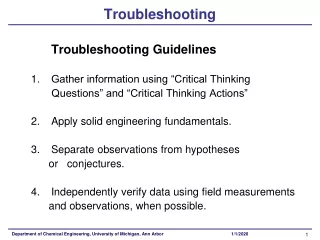
Electronic Troubleshooting
Electronic Troubleshooting. Chapter 5 Multistage Amplifiers. Overview. When more amplification is required than can be supplied by a single stage amp A second stage is added Or more stages are added Aspects that are covered Capacitively Coupled Stages Testing and Troubleshooting

Electronic Troubleshooting
E N D
Presentation Transcript
Electronic Troubleshooting Chapter 5 Multistage Amplifiers
Overview • When more amplification is required than can be supplied by a single stage amp • A second stage is added • Or more stages are added • Aspects that are covered • Capacitively Coupled Stages • Testing and Troubleshooting • Frequency Response of Cascaded Stages • Using Negative Feedback • Direct Coupled Amplifiers
Overview • Aspects that are covered • Differential Amplifiers • Emitter Followers • Analysis of a Complete Amplifier System
Two Stage Capacitively Coupled • Characteristics • Two stages coupled by • Cap – CC • Freq of AC signal under amplification • High enough to yield insignificant impedance, XC for CC • Determining impedance seen by AC signals • DC Power supplies appear as a ground/common • Equivalent impedance seen by the output of Q1
Two Stage Capacitively Coupled • Characteristics • Gain of the first stage AV1 = rL1/re1 • Gain of the second stage AV2 = rL2/re2 • Total Gain AV(tot) = AV1 x AV2 • Sample Problem • Given: vin = 2mV, AV1 = 40, AV2 = 60 • Find voltages at points X and Y on the drawing
Testing a two-stage amplifier • Check the output of the last stage • Should have non-distorted signal of appropriate magnitude • If bad check at the output of each stage • Remove from consideration all properly functioning parts of the circuit
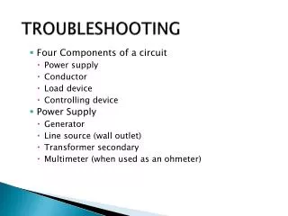
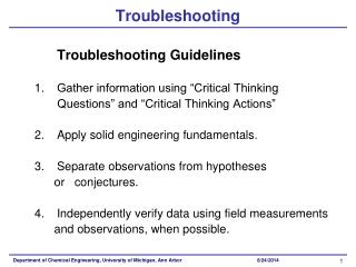
Troubleshooting Cascade Stages • Test the power supply voltages – If Good ↓ • Insert small AC signal • Signal Characteristics • Few millivolts • Into first stage • Follow the testing chart • Page 95 and 96 • Quickly sets focus on defective part of circuit • Divide and fix strategy • Walk through assuming R2 is an open – 3rd para on page 97
Frequency Response of Cascaded Stages • Frequency response of amplifiers is limited • At both high and low frequencies around the operating band • Low Freq limiting • Attenuation of the output is directly related to the increasing impedance of CC as the Freq of the input is decreasing • As can be seen in the coupling circuit to the right • XC at lower freq decrease the input signal for the second stage • At DC CC is an open
Frequency Response of Cascaded Stages • Frequency response of amplifiers is limited • Low Freq limiting • A Thevenin equivalent circuit simplifies the analysis • When XC = RC1 + r in(2nd stage) • Vin to the second stage is 0.707 of its max • Power delivered is ½ or -3dB • The freq at which this happens is the lower -3dB point or f1 • Example Problem • See middle of page 98
Frequency Response of Cascaded Stages • Freq response of amplifiers is limited • High Freq limiting • Shunting Caps cause high frequency limiting • Q1 shunted by CCE • Q2 input shunted by CBE or Cin • The composite shunting Cap for all the coupling circuit wiring • CS is the parallel combination • Same for Req • f2 is the freq at which XC = Rt • The half power point or -3dB point • See example problem • Mid-page on 99
Frequency Response of Cascaded Stages • Amplifier Frequency Response Curve
Distortion Reduction –Negative Feedback • Prime Cause – Large driving signal • Results of such distortion are illustrated below • Unequal positive and negative transitions on the output
Distortion Reduction –Negative Feedback • Prime Cause – Large driving signal • Distortion results from the characteristics of the base-emitter diode • The characteristic curve is only linear over a small range • See the negative transition of Ib • Will yield • Distorted Ic • Distorted vO
Distortion Reduction –Negative Feedback • Negative Feedback • Characteristics • Supplies fraction of the output back to the input • Connection to the emitter yields negative feed back • Feedback voltage scaling • Voltage divider of RE and RF
Distortion Reduction –Negative Feedback • Negative Feedback • Effects of negative feedback • Pre-distorts the output of the first stage to yield an undistorted output from the second stage • Will help counter act the distortion generated in the second stage • IC and collector voltage VQ1 will have the same form
Distortion Reduction –Negative Feedback • Negative Feedback • Effects of negative feedback • The more feedback the less distortion • However the more feedback the less gain • Gain with Feedback • Called Closed Loop Gain • When open loop gain (without feedback) is large compared to closed loop gain • At least a factor of 10 or more between Open and Closed loop gain
Direct Coupled Amplifiers • Characteristics • Used when low frequency or DC signals are amplified • For example DC signals in a power regulator, or the outputs of thermocouples • Simple circuit (typical of Output stages) • Transistor current controlled by VRE Can be changed by: • Changing RE or VE
Direct Coupled Amplifiers • Simple Amp without Feedback • Characteristics • AV1 =RC1/re1 , AV2 =RC2/RE2 , AV2 is usually much smaller than AV1 • Problems with circuit • As Q1 temperature increases • IC increases • VC(Q1) decreases • Changes are amplified by Q2 • Direct coupling increases temperature instability
Direct Coupled Amplifiers • Simple Amp with Feedback • Characteristics • Forward biased on Q1 comes from VRE • Divided by R1 and R2 • Follow startup • Q1 off VB(Q2) goes positive • Q2 turns on and VE grows • VB(Q1) goes positive • Q1 turns on • IRC1 increases, VB(Q2) decreases • VB(Q1) reaches 0.7V quickly • At stability VRE depends on the ratio of R1 & R2
Direct Coupled Amplifiers • Simple Amp with Feedback • Characteristics • Temperature Stability • Q1 heats up and IC1 increases • VC1 and VB2 decreases • VE decreases, thus VB1 decreases • Q1 then conducts less • Thus VC1 increases • End result a temperature change causes less change in output • CE was added to make a good low frequency Amp • No effect on DC input signals
Direct Coupled Amplifiers • Simple Amp with Feedback • Characteristics • Temperature Stability • Q1 heats up and IC1 increases • VC1 and VB2 decreases • VE decreases, thus VB1 decreases • Q1 then conducts less • Thus VC1 increases • End result a temperature change causes less change in output • CE was added to make a good low frequency Amp • No effect on DC input signals
Direct Coupled Amplifiers • Real Sample Circuit • See Figure 5-14 on page 106 • Walk-through • Collector of transistor X101 is direct coupled to Base of X102 • Base of X101 is biased off of R114 through R104 –Temp Stability • What is the circuit that links the collector of X102 to the emitter of X101?
Differential Amplifiers • Characteristics • Used to amplify differences between two signals • Can use transistors, Tubes, or Linear ICs • This chapter deals with the transistor version • Requires two identical transistors and a common emitter resistor • Both are forward biased • -15 Supply • Both emitters at -0.7V • Both IE’s ~ 1mA • Both collectors = 10V and VD =0V
Differential Amplifiers • Characteristics • Temperature stability • Due to identical transistors if the temperature rises both have the same current increase and VD stays the same • Walk through • One input has a more positive value • That transistor conducts More, VE increases, VC decreases • The other transistor conducts less and VC Increases • VD is proportional to the inputs but larger • Example problem on top of page 108
Differential Amplifiers • Characteristics • Walk through • Impractical to use very high voltage supplies • Use a constant current source instead • RE can be adjusted for a more accurate current amount
Emitter Followers • Characteristics • Have unity gain • Output in phase with Input • No collector resistor • Output from emitter • Provides current gain without loading the input circuit • RE = RL for given circuit • rin = 80 x 1kΩ
Emitter Followers • Actual Circuits • Load for the DC Amp • VQ1 sees 5K Ω ||30KΩ • The output can drive a 3KΩ with less than 10% change in output