Download
1 / 29
310 likes | 664 Views
Bus Arbitration, DMA, and Bus Mastering. Jason Bennett, Tom DiLello, Anthony Sofia. CMSC 415 Computer Architecture Jim Teneyck 4/23/02. What is Bus Arbitration, Bus Mastering and DMA?.

E N D
Bus Arbitration, DMA, and Bus Mastering Jason Bennett, Tom DiLello, Anthony Sofia CMSC 415 Computer Architecture Jim Teneyck 4/23/02
What is Bus Arbitration, Bus Mastering and DMA? • Bus Arbitration – an elaborate system for resolving bus control conflicts and assigning priorities to the requests for control of the bus. • Bus Mastering – a method of enabling different device controllers on the bus to ‘talk’ to one an other, without having to go through the CPU. • DMA(Direct Memory Access) – a method of transferring data from a hard disk to main memory without having to go through the CPU.
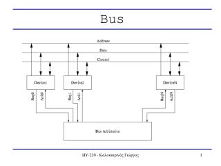
Bus Arbitration Methods • Centralized Centralized bus arbitration requires hardware (arbiter)that will grant the bus to one of the requesting devices. This hardware can be part of the CPU or it can be a separate device on the motherboard. • Decentralized Decentralized arbitration there isn't an arbiter, so the devices have to decide who goes next. This makes the devices more complicated, but saves the expense of having an arbiter.
Centralized Bus Arbitration • Centralized One Level Bus Arbiter • This method of arbitration uses one centralized bus controller that all devices can query. • Centralized Two Level Bus Arbiter • Uses a Bus Request Line and Bus Grant Line for each Level
Centralized One Level Bus Arbitration This method of arbitration uses one centralized bus controller that all devices can query. There are 2 lines that are used: 1. Bus Request Line – A wired ‘OR’ that the controller knows a request was made, but does not know which device made the request. 2. Bus Grant Line – First a signal is propagated to all devices. The Bus Grant Line is asserted to the first device in the chain. If that device made the request it takes a hold of the bus and leaves the Bus Grant Line negated for the next device in the chain. If that device didn’t make the request then the Bus Grant Line is asserted for the next device in the chain. If two devices make a request for the bus at the same time then the device closer to the controller gets the bus. This is called daisy chaining
Centralized Two Level Bus Arbitration • Centralized Two Level Bus Arbiter • Bus Request line: one for each level • Bus Grant line: one for each level This Helps to alleviate the problem of the closest device to the controller getting control of the bus. If more than one request comes in at one time, control is granted based on priority. One major advantage to this is when a lower priority device has control of the bus, a higher priority device cannot ‘steal’ the bus from that device.
Micro Channel Bus - Centralized Two Level Bus Arbiter • An MCA (micro channel architecture) bus is an example of a centralized two level bus arbiter • Has control built-in to make sure that no properly designed device can be unwillingly locked out of bus access. • This flexibility of the Micro Channel arbitration process is a result of making several divergent functions work together. These include preemption, fairness, linear priority, bus time-out, latency, and system board priority. • Implements a priority system in which the Micro Channel adds several new lines to the PC bus. Four of these, lines 0 – 3, are added to yield 16 different priorities. • In addition, two additional levels of priority are used by the devices on the system board of the PS/2 and do not appear on the Micro Channel. These special internal levels are used to assign the absolute top priority to memory refreshing and nonmaskable interrupt.
Decentralized Bus Arbitration Def’n: Decentralized Bus arbitration does not require an arbiter so the devices have to decide who gets control of the bus. The devices therefore have to be more complicated, but this saves the expense of having an arbiter. • VAX SBI Bus The VAX by DEC has 16 separate request lines. All Devices monitor on all the lines. If they want to send data they determine if another device with a priority is using the bus. • Multibus uses three lines: an Arbitration line, Busy line, and a Bus Request Line
Decentralized bus arbitration – Vax SBI Bus • All devices monitor the bus, when a device wishes to use the bus, it makes sure that no other higher priority device is using the bus. If not then is begins its transmission, if not it waits till the devices is done transferring to begin its transfer. • Q: When does a device negate its request line? • A: When its request is completed • Q: How does a device determine that whether or not the bus is in use? • A: By seeing if another higher priority device has requested it. When all is clear, that device will negate its request line.
Decentralized bus arbitration – Multibus • Arbitration line This line can also be dubbed the ‘IN’ line. When this line is asserted the device knows is has been granted the bus. If this line is negated then permission has not been granted to the device. When no device is using the bus all devices get the asserted ‘IN’ line, meaning anyone can use the bus. When the device attempts to grab the bus it asserts its ‘OUT’ or Bus request line. • Busy once a device has determined that no other device is using the bus, or a device with a higher priority is using the bus it asserts this line, deemed the ‘BUSY’ line. This will let all other devices that this device is using the bus. Once the ‘BUSY’ line is asserted, the ‘OUT’ line is asserted. • Bus Request This line indicates whether another device has made a request. If Busy is negated, then the device negates OUT and waits an undetermined amount of time to see if its IN will be negated.
Bus Mastering Def’n:Refers to a feature supported by some bus architectures that enables a controller connected to the bus to communicate directly with other devices on the bus without going through the CPU. Normally, the processor is required to control the transfer of this information. In essence, the processor is a "middleman", It is far more efficient to "cut out" the middleman and perform the transfer directly. This is done by having capable devices take control of the bus and do the work themselves. In theory this frees up the processor to do other work simultaneously.
Different Bus Architectures • ISA (Industry Standard Architecture) • MCA (Micro Channel Architecture) • EISA (Extended Industry Standard Architecture) • VLB (Vesa Local Bus) • PCI (Peripheral Communications Interconnect)
ISA (Industry Standard Architecture) • Bus mastering really hasn’t been successful with the ISA bus. Any ISA device can take control of the bus, but it must be done with caution. There are no safety mechanisms involved, so if a device incorrectly takes control of the bus, it may crash the system. For example, we all know the DRAM needs to be refreshed periodically. If the ISA bus master doesn’t relinquish control of the bus every 15 ms, to generate its own DRAM refresh, the DRAM will become corrupted. • To take control of the bus, the device first asserts its DRQ line. The DMAC sends a hold request to the CPU, and when the DMAC receives a hold acknowledge, it asserts the appropriate DAK line corresponding to the DRQ line asserted. The device is now the bus master. AEN is asserted, so if the device wishes to access I/O devices, it must assert MASTER16 to release AEN. Control of the bus is returned to the system board by releasing DRQ.
MCA (Micro channel Architecture) • The MCA bus was IBM's attempt to replace the ISA bus with something "bigger and better". When the 80386DX was introduced in the mid-80s with its 32-bit data bus, IBM decided to create a bus to match this width. MCA is 32 bits wide, and offers several significant improvements over ISA. (One of MCA's disadvantages was rather poor DMA controller circuitry.) • The main idea behind the MCA bus was, instead of constraining the computer to working on one problem at a time, multiple problems can be approached simultaneously. It allows the bus to be used by two or more bus masters at the same time, by setting up a control system for coordinating their operations. • The way this is accomplished is by using a master/slave concept. If two or more devices via-ing for the bus. The bus slave functions just as an ordinary expansion device in a non-mastering PC. The difference between the bus master and the bus slave is entirely functional. In the MCA scheme one bus master can take control over another, making the second its slave. Later the two devices can reverse their roles when another situation demands it.
MCA (Micro channel Architecture, cont’) • The MCA bus had some pretty impressive features: • 32 bi wide bus: impressive considering it was introduced in 1987. Had far superior throughput than the ISA bus. • PnP (Plug and Play): MCA automatically configured adapter cards, so there was no need to fiddle with jumpers. This was eight years before Windows 95 brought PnP into the mainstream. • MCA had a great deal of potential. Unfortunately, IBM made two decisions that would doom MCA to utter failure in the marketplace. First, they made MCA incompatible with ISA; this means ISA cards will not work at all in an MCA system. The PC market is very sensitive to backwards-compatibility issues, as indicated by the number of older standards that persist to this day. Second, IBM decided to make the MCA bus proprietary. It in fact did this with ISA as well; however in 1981 IBM could afford to flex its muscles in this manner, while by this time the clone makers were starting to come into their own and weren't interested in bending to IBM's wishes.
EISA(extended Industry Standard Architecture) • Introduced in 1987, the EISA bus was AST Research’s, Compaq’s, Epson’s, Hewlett Packard’s, NEC’s, Olivetti’s, Tandy’s, WYSE’s, and Zenith Data Systems’s answer to IBM’s MCA Bus. The EISA Bus provided 32-bit slots at an 8.33 MHz cycle rate for the use with 386DX, or higher processors. • Some of the Key features of this bus are: • ISA Compatibility: ISA cards would work in EISA slots. • 32 bit bus: Like MCA this bus was expanded to 32 bits. Giving it a throughput of 31.8 MBs • Bus Mastering: supported bus mastering cards for greater performance, including bus arbitration • PnP: EISA automatically configures adapter cards, similar to the Plug and Play standards of modern systems. • There were two main reasons for the downfall of the EISA bus architecture: • 1: EISA based systems tended to be more expensive • 2: There just weren’t many EISA-based cards available
VLB “VESA Local Bus”(Video Electronics Standards Association) bus • The VESA (Video Electronics Standards Association) a nonprofit organization founded by NEC, released the VLB or VESA Local Bus in 1992. The VLB is a 32-bit bus that gave direct access to the system memory at the speed of the processor, commonly the 486 CPU. Unfortunately, because the VLB heavily relied on the 486 processor when the Pentium Processor arose in the Market place. • The VLB is in a way a direct extension of the 486 processor/memory bus. A VLB slot is a 16-bit ISA slot with third and fourth slot connectors added on the end. The VLB normally runs at 33 MHz with a total Bandwidth of 127.2 MBs, although higher speeds are possible on some systems. Since it is an extension of the ISA bus, an ISA card can be used in a VLB slot, although it makes sense to use the regular ISA slots first and leave the (small number of) VLB slots open for VLB cards, which won't work in an ISA slot of course. Use of a VLB video card and I/O controller greatly increases system performance over an ISA-only system. • Four reasons for its downfall were: • 1: The bus was heavily based on Intel’s 486, so adapting it to the Pentium was difficult • 2: Tricky electronics. Not many cards could be supported on the bus, namely one or two. And even when more than one expansion card was used, there were timing problems • 3: No bus arbitration scheme • 4: No PnP support
PCI (Peripheral Communications Interface) • Introduced by Intel in 1992, revised in 1993 to version 2.0, and later revised in 1995 to PCI 2.1. It’s a 32-bit bus that is also available as a 64-bit bus today. It can run @ 33MHz with a bandwidth of 127.2 MBs or @64 MHz with a bandwidth of 508.6 MBs. • The key to PCI's advantages over its predecessor, the VESA local bus, lies in the chipset that controls it. The PCI bus is controlled by special circuitry in the chipset that is designed to handle it, where the VLB was basically just an extension of the 486 processor bus. PCI is not married to the 486 in this manner, and its chipset provides proper bus arbitration and control facilities, to enable PCI to do much more than VLB ever could. PCI is also used outside the PC platform, providing a degree of flexibility and allowing manufacturers to save on design costs. • The PCI bus also allows you to set up compatible IDE/ATA hard disk drives to be bus masters. To get this to work 4 things must be present: • 1: Bus Mastering Capable System Hardware: This includes the motherboard, chipset, bus and BIOS. Most newer motherboards using the Intel 430 Pentium chipset family (FX, HX, VX, TX) or the Intel 440FX Pentium Pro chipset, will support bus mastering IDE. • 2: Bus Mastering Hard Disk: Normally this means that the drive must be capable of at least multiword DMA mode 2 transfers. All Ultra ATA hard disks support bus mastering. • 3: A32-Bit Multitasking Operating System: Windows NT, Windows 95, Linux, or similar • 4: Bus Mastering Drivers: A special driver must be provided to the operating system to enable bus mastering to work..
DMA (Direct Memory Access) • DMA(Direct Memory Access): DMA is a feature supported by some bus architectures that allows data to be transferred to and from RAM without burdening the CPU. This is accomplished by a DMA controller chip. In addition some add-on cards need to transfer data to the systems memory through a DMA channel. Each expansion card which supports DMA uses at least one DMA channel. The PC supports up to 7 DMA channels (though some of these are not compatible with all expansion cards). No two expansion cards can be using the same DMA channel at the same time (and only a few cards support sharing of a DMA channel when they are not using it). You must select a DMA channel which is not used by another card installed in the computer (sound cards frequently use one or even two DMA channels), and configure it for that DMA channel. If you accidentally choose a DMA channel which another card is using, the symptom is usually that no DMA transfers take place. No data is acquired or if the conflict is with a sound card, sounds may not play.
DMA (cont’) • How is works:The peripheral (a LAN adapter, for example) writes from its memory directly to the PC's memory in one bus cycle (reducing the load on the bus), rather than the two-step process of the CPU's DMA controller first reading the data (from the adapter) and then writing it to the PC's memory in a second bus cycle. • Often, the adapter will do its transfer as the data are received from the LAN, so no, or little, on-board LAN adapter memory is required (this saves money). • Uses much less CPU time than other methods. For example, programmed input-output (PIO) requires the CPU to first check for the availability of the data, then read the data, and then write the data. This requires bus and CPU time for both fetching the CPU's instructions and for reading and writing the data. Also, bus master DMA is faster than standard DMA, since the CPU does not even need to load the DMA registers (for example, with the source and destination addresses) to set up each transfer.
IBM 370 Channel • Channels are an extension of the Direct Memory Access (DMA) function. • A channel directly executes instructions, this gives it complete control over the operation. • The main system processor is not used during the execution of the instruction, but rather instructions are stored in main memory, where they wait to be executed by the channel’s own processor. • The CPU initiates the instruction by telling the channel to execute a program. • The two most common types of channel architectures are the selector and the multiplexor. • Selectors can control more than one device, but can only talk with one at a time. Each device has a corresponding controller that is managed by the channel, rather than the CPU. • Multiplexors: can also control more than one device. There are a couple types of multiplexor channels. A byte multiplexor accepts or transmits characters as fast as possible to multiple devices. A block multiplexor used with high-speed devices, alternates blocks of data from several devices.
370 Channel Control • The CPU can control one or more channels, which can be byte or block multiplexors. • Each channel contains one or more controllers, called control units. • A control unit is usually in charge of a set of similar or identical devices. For example - a disk controller could control several disk drives. • It is possible for one control unit to be connected to several channels and for one device to be connected to several control units. • This allows more than one physical path between the CPU and a device. • This is important, if one pathway is busy or disabled, an alternate route may be found.
370 I/O Addressing • The IBM 370 architecture uses an isolated I/O addressing scheme to reference connected devices. • Addresses on the 370 are 24 bits and device addresses are only 16 bits. • The leftmost eight bits are set to zero. • Eight bits are used to designate the channel allowing up to 256 channels. • The next four bits indicate the control unit in the channel. • The last four bits designate the device within the control unit. • When more than one routes are available, then a device will have a different address for each path.
Channel Instruction Execution • When an I/O instruction is executed the CPU sends a command to the channel, which contains three things. • Opcode • Control Unit • Device Address • When an I/O operation is started the channel reads the Control Access Word (CAW) from location 72 of main memory. • Memory address 72 is written by the program that called for the execution of the operation. • The Channel Command Word (CCW) is fetched and decoded by the channel. • The I/O program can be made up of one or more CCW, all of which must already be stored in main memory. • A CAW is made up of the following three fields. • 1: Key: A 4-bit access key is associated with every 2K or 4K-byte block of memory. The key in the CAW is used by the channel whenever a reference is made to a main memory location during the I/O process. • 2: S bit: When set indicates that it is possible for the CPU to suspend and later resume the I/O process. • 3: CCW Address: The location of the first CCW to be used for this operation.
370 Control Command Words • Channel programs that are made up of one or more CCW are held together using branching and chaining. • They can be chained together using either data or command chaining. • In both cases when the command has finished executing the channel will get the next CCW in the sequence. • A CAW is made up of the following four fields. • 1: Command Code: Essentially the opcode. It tells the channel what type of operation to perform. The Command Codes include modifier bits that are device specific. • 2: Data Address: Specifies the starting location in memory for a data transfer. • 3: Flags: Specify additional information about the operation to be performed. • 4: Count: Specifies the number of bytes to be transferred in this operation.
IBM 370 I/O Channel Instructions • Start I/O (SIO): Used for initializing an input/output operation that involves sensing the status if a device, controlling the device, and data transfer between the device and the main storage. This instruction causes an I/O channel to fetch a Channel Address Word that will begin the I/O operation. The SIO instruction is initiated if both the subchannel and device are available, and the channel is available or the interruption-pending state and errors have not been detected. The CPU is not released until the above conditions are checked and the device is selected. • Start I/O fast release (SIOF): Similar to SIO and used on block multiplexor channels. The main difference is that with SIOF, the CPU is released as soon as the Channel Address Word (CAW) is fetched by the I/O processor. • Test Channel (TCH): Tests whether the channel is operational or not, if it is operating in burst mode, and has a any pending interrupt requests. This is primarily used to monitor performance. • Test I/O (TIO): Tests the status of not only the channel, but also the subchannel and the device. This instruction is used to monitor status or to respond to an interrupt. • Store Channel ID (STID): Used to obtain information about an addressed channel, such as channel type (selector, byte multiplexor, block multiplexor), and model number.
IBM 370 I/O Channel Instructions (cont’) • Halt I/O (HIO): Causes the current I/O operation to be halted. A channel, subchannel, or device may be specified. This instruction provides the CPU with a means of terminating an I/O operation before all data have been transferred. This could be done to free a selector channel for a higher-priority operation, or to provide real-time control on a multiplexor channel. • Halt Device (HDV): Similar to HIO. Used primarily on block multiplexor channels to halt a specific device without interfering with other channel operations in progress. • Clear I/O (CLRIO): Serves the same purpose as TEST I/O, and is used instead of TEST I/O for block multiplexor channels. The Clear I/O instruction may also cause an I/O operation to be suspended pending interrupt processing. • Clear Channel (CLRCH): Causes the Channel to conclude operations on all subchannels. Status information and interruption conditions are reset on all subchannels, and a reset signal is issued to all assigned I/O devices. • Resume I/O (RIO): Causes a currently suspended channel-program execution to be resumed with the device
IBM 370 I/O Interface Control Lines • Bus Out (9): Used to transmit addresses, commands, control orders, and data to the control units. Consists of eight information lines and one parity line. • Bus In (9): Used to transmit addresses, status, sense information, and data to the channel. Consists of eight information lines and one parity line. • Outbound Tags (3): Identify the type of information present on BUS OUT. The correspondence is the control unit ADDRESS OUT, the command COMMAND OUT, and data requested by the control unit SERVICE OUT. • Inbound Tags (3): Identify the type of information present on BUS IN. The correspondence is the address of responding control unit ADDRESS IN, status information STATUS IN, and data associated with the current I/O operation SERVICE IN. • Scan Controls (4): Used for polling and selection of control units. SELECT OUT and SELECT IN form a loop from the channel through each control unit and back. HOLD OUT provides synchronization, REQUEST IN indicates that the control unit is ready to present status information or data and is requesting a selection sequence. • Interlocks (2): Used to ensure that only one control unit is communicating with the channel an any given time. OPERATIONAL OUT must be up for the other lines to have significance. When it is down, all lines must drop any operation currently in progress and must be reset. OPERATIONAL IN signals the channel that the control unit is selected and communicating. • Special Controls (4): Used for metering time, suppressing other lines, and other specialized control purposes.
Bibliography • http://www.pcguide.com/ref/mbsys/buses/types/index.htm • http://www.webopedia.com • Heath, Chet and Rosch, L. Winn The Micro Channel architecture. Simon & Schuster, Inc., 1990. • Cormier, R., Dugan, R., Guyette, R. "System/370 Extended Architecture: The Channel Subsystem" IBM Journal of Research and Development. May 1983. • IBM Corp. IBM System/370: Principals of Operation. GA22-7000-9. May, 1983. • IBM Corp. IBM System/370 Extended Architecture: Principals of Operation. SA22-7085-0. May, 1983.