Download
1 / 1
10 likes | 196 Views
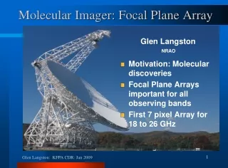
Introduction. KATRIN and FPD Detector Housing. The Vacuum Design of the FPD. Monte-Carlo Modelling for System Design. Vacuum Design for the Focal Plane Detector (FPD) of KATRIN. Keith J Middleman ASTeC, STFC Daresbury Laboratory, Warrington, Cheshire, WA4 4AD, UK

E N D
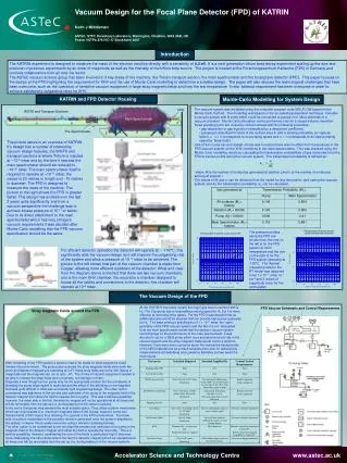
Introduction KATRIN and FPD Detector Housing The Vacuum Design of the FPD Monte-Carlo Modelling for System Design Vacuum Design for the Focal Plane Detector (FPD) of KATRIN Keith J Middleman ASTeC, STFC Daresbury Laboratory, Warrington, Cheshire, WA4 4AD, UK Poster VSTP4-276IVC-17 Stockholm 2007 The KATRIN experiment is designed to measure the mass of the electron neutrino directly with a sensitivity of 0.2 eV. It is a next generation tritium beta-decay experiment scaling up the size and precision of previous experiments by an order of magnitude as well as the intensity of the tritium beta source. The project is located at the Forschungszentrum Karlsruhe (FZK) in Germany and involves collaborators from all over the world. The ASTeC vacuum science group has been involved in 3 key areas of the machine, the Tritium transport section, the main spectrometer and the focal plane detector (FPD). This paper focuses on the design of the FPD highlighting the requirement for XHV and the use of Monte-Carlo modelling to determine a suitable design. The paper will also discuss the technological challenges that have been overcome, such as the operation of sensitive vacuum equipment in large stray magnetic fields and how the low temperature ‘in-situ’ bakeout requirement has been overcome in order to achieve satisfactory outgassing rates for XHV. • The vacuum system was modelled using the computer program code MOLFLOW based on the Monte-Carlo method. The modelling was based on the so-called superposition technique. Consider a vacuum system with N ports which could be connected to pumps or to other elements of a vacuum chamber. Monte-Carlo simulation can be performed only for a closed volume; therefore these pumping ports are closed by virtual surfaces with the following properties: • gas desorption or gas injection is described by a desorption coefficient, • pumping is described in terms of the surface area A, and a sticking probability (or capture factor) . = 0 corresponds to no pumping speed and = 1 corresponds to an ideal pumping speed (a “black hole”). FPD WGTS and Transport Sections Main Spectrometer Pre-Spectrometer The picture above is an overview of KATRIN. It’s design has a number of interesting vacuum design features, the WGTS and transport sections is where Tritium is injected at ~10-3 mbar and by the time it reaches the main spectrometer should be reduced to ~10-20 mbar. The main spectrometer itself is required to operate at <10-11 mbar, the vessel is 23 metres in length and ~10 metres in diameter. The FPD is designed to measure the mass of the neutrino. The picture to the right shows the FPD in greater detail. This design has evolved over the last 2 years quite significantly and from a vacuum perspective the challenge was to achieve a base pressure of 10-11 or better. Due to its direct attachment to the main spectrometer which has very stringent vacuum requirements it was decided after Monte-Carlo modelling that the FPD vacuum specification should be the same. One of the crucial vacuum design criteria was to ensure there was no effect from the pressure in the FPD vacuum system on the XHV conditions in the main spectrometer. This was checked using the Monte-Carlo modelling results by calculating the transmission probabilities of gas molecules from the FPD to various points along the vacuum system. The transmission probability is defined as: where Mj is the number of molecules generated at position j and ni is the number of molecules arriving at position i. The values of Mj and ni can be obtained from the model for any two points i and j along the vacuum system, and so the transmission probability wi,j can be calculated. The pressure profiles along the FPD are shown here, the one on the left is for the FPD system at room temperature and the one on the right is for the FPD system operating at -100°C. The thermal outgassing rate for the RT model was assumed to be 1 x 10-11 mbar l s-1 cm-2 and 2 orders of magnitude lower for the cold system. For efficient detector operation the detector will operate at ~ -100°C, this significantly aids the vacuum design as it will improve the outgassing rate of the system and allow a pressure of 10-11 mbar to be achieved. The picture to the left shows how part of the vacuum chamber is made from Copper, allowing more efficient cooldown of the detector. What isn’t clear from the diagram above is the fact that there are two vacuum chambers, one is the main XHV chamber, the second is a chamber designed to house all the cables and connections to the detector, this chamber will operate at 10-6 mbar. At the UHV/XHV boundary usually the major gas load to contend with is H2. The Cryopump has a reasonable pumping speed for H2 but it is more effective at removing other gases. For the FPD it was decided that an additional pump would be required that can provide high pumping speeds for H2. The base pressure specification of 1 x 10-11 mbar, the ‘open’ geometry of the FPD vacuum system and the fact it is not ‘decoupled’ from the main spectrometer meant that the detector vacuum system could impinge on the performance of the main spectrometer. It was decided to opt for a NEG pump which once activated would sit idly in the vacuum system and the stray magnetic fields would not be a problem. However, there were some concerns about the radioactive backgrounds of the NEG material and as a result samples were sent for radioactivity measurements at Heidelberg and Lawrence Berkeley and we await the final results. FPD Vacuum Schematic and Control Requirements Stray magnetic fields around the FPD After modelling of the FPD system a decision had to be made on what equipment could tolerate the environment. The picture above shows the stray magnetic fields when both the pinch and detector magnets are operating at 3.3T, these stray fields are some 300 Gauss in magnitude and the magnets can run at upto ~6T. The choice of vacuum equipment needed to be able to tolerate the stray fields and conversely, not impinge on them. Originally it was thought an ion pump may be the appropriate solution but the complexity of shielding the pump when space is restricted and the effect of the shielding on the magnetic field was quite difficult in what was an already tight engineering design. The other option considered was alignment of the anodes and cathodes of ion pump in the magnetic field of the detector magnet and utilise the field to operate the ion pump. This was a definite possibility, however, the down side is the fact the detector magnet will not be operational at all times and will be removable from the set-up (i.e. during bakeout of the vacuum system). In the end a Cryopump was deemed the most suitable option. They utilise a piston mechanism which can only operate in a maximum magnetic field of 300 Gauss, however, some can tolerate fields of 500 Gauss thus allowing it to operate in the FPD environment. The down side of a piston mechanism is the possible vibration generated once the pump is attached to the system, however this is easily overcome using a vibration damping bellows. The other option to be considered is can we align the anodes and cathodes of ion pump in the magnetic field of the detector magnet and utilise the field to operate the ion pump. This is a definite possibility, however, considering the size of the fields is particularly high it becomes more challenging, the other down side is the fact the detector magnet will not be operational at all times and will be removable from the set-up (i.e. during bakeout of the vacuum system).