Advanced FPD Trigger Electronics Overview: Components and Configuration
This document outlines the extensive architecture and operational components of FPD trigger electronics, detailing two distinct runs: Surplus Run I and Standard Run II. It includes diagrams for key boards such as AFE, DFE, and the AMP/Shaper modules, specifying their configurations. The intricacies of various interfaces such as LVDS, coaxial cables, and fiber optics are discussed, alongside the implications for system integration involving multiple boards, tubes, and test setups like CAMAC event testers. A comprehensive overview for researchers and engineers in the field of high-speed electronics.

Advanced FPD Trigger Electronics Overview: Components and Configuration
E N D
Presentation Transcript
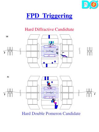
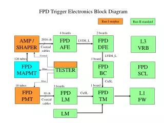
FPD Trigger Electronics Block Diagram Run I surplus Run II standard 4 boards 2 boards FPD AFE FPD DFE AMP / SHAPER L3 VRB 2016 ch LVDS_L Coaxial cables LVDS_L Coaxial 126 tubes 1 board FPD MAPMT FPD BC TESTER FPD SCL Fiber CuSL Fiber 1 board 18 tubes 3 boards FPD PMT FPD TM FPD LM L1 FW CuSL 18 ch Coaxial cables LM
FPD Standalone Trigger Electronics Run I surplus Temporary FERA ADCs AMP / SHAPER 192 ch Coaxial cables Coaxial 12 tubes FPD MAPMT CAMAC EVENT TESTER D0OL13 PC Fiber Fiber 6 tubes FPD PMT CAMAC TRIGGER NIM+ CAMAC 6 ch Coaxial cables L0