Download

1 / 52
520 likes | 677 Views
Pipelining. Levels of Instructions. One high-level Many assembly-level Recall that a single line of code in a high level language may result in several instructions at the assembly/machine-code level. One assembly-level Many micro-code

E N D
Levels of Instructions • One high-level Many assembly-level • Recall that a single line of code in a high level language may result in several instructions at the assembly/machine-code level. • One assembly-level Many micro-code • Furthermore, one assembly/machine-code instruction consists of several micro-code instructions.
Micro-coding Load Accumulator A • Recall the our very naïve architecture and the micro-coding of a simple assembly-level instruction, Load Accumulator A, for that architecture.
Bus (Naïve Architecture) Keyboard encoder Input port 1 Accumulator Flags ALU Input port 2 Prog. counter TMP Mem.Add.Reg. B Memory C MDR Output port 3 Display Instr. Reg. Output port 4 Control
Address State: the value of the program counter (which recall is the address of line of the program to be performed) is put into memory address register.
Increment State: the program counter is incremented, getting it ready for the next time.
Memory State: the current line of the program is put into instruction register (so Control knows what to do).
Recall the instruction consisted of a load command and an address. A copy of the address is now taken over to the memory address register.
For the load command, there is no activity during the sixth step. It is known as a "no operation" step (a "no op" or "nop").
These 1’s and 0’s are MICRO-CODE. • A large part of processor design is to get this micro-code to execute as efficiently as possible.
Instruction Review • There are many registers so the Load instruction might be more like LD r5, (r6) • Load Register 5 with the value at the address in Register 6. • An Add instruction might be ADD r1, r2, r3 • Add the values in Registers 2 and 3 and place the result in Register 3
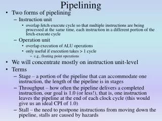
Stages • The micro-code steps that go into making an assembly-level instruction can be thought of as belonging to various stages: • Fetch Instruction • Decode Instruction • Read Registers • Execute Instruction • Write Result Back to Registers • (Look for interrupt?)
Stages and Units • The pipeline is said to be broken into stages. • So one talks about the Fetch Instruction (FI) stage. • The terms section and/or segment are sometimes used in place of stage. • The circuitry responsible for a stage is known as a unit. • So one talks of the Fetch Instruction (FI) Unit.
Idle hands • Early processors executed one instruction (all of its stages) at a time. • Recall the von Neumann bottleneck. • In this approach, most of the processor’s parts are inactive most of the time.
Note in the micro-code above we assumed 1 was active and that most of the entries are 0’s.
Toward Efficiency • Division of Labor: • “A production process in which a worker or group of workers is assigned a specialized task in order to increase efficiency.” • Assembly Line: • “An arrangement of machines, tools, and workers in which a product is assembled by having each perform a specific, successive operation on an incomplete unti as it passes by in a series of stages organized in a direct line.” • (Webster’s)
Pipelining • Applying the assembly line idea to a processor’s execution of instructions is known as pipelining. • The instruction is broken into various stages and instead of having one instruction complete all stages before the next is begun, several instructions are being executed at once – each in a different stage. • The stages are separated by latches, which prevent information from one stage to pass prematurely into the next stage.
Slower but faster • The introduction of the stages separated by latches actually slows down the execution of a single instruction. • However, there is an overall gain in speed since many instructions are in the midst of being processed simultaneously.
Staying in sync and the weakest link • The stage that takes the longest will determine the speed of the entire process. • All of the other stages must wait for this stage to complete before information is passed to the next stage. • The processes should be broken into stages that at much as possible take the same amount of time.
For example • If you broke a 26-second process into five stages: four of them taking 5 s and one taking 6 s. • Then it would take 30 s for an individual instruction to move through the pipeline. • However, one instruction would be coming out of the pipeline every 6 s. • Compared to one instruction every 26 s without pipelining.
Sample question • If a 32-second process were broken into 8 stages, (3 requiring 3 seconds, 3 requiring 4 seconds, 1 requiring 5 seconds and 1 requiring 6 seconds), then it would take ______(number of seconds) for an instruction to move through the pipeline as opposed to the original 32 seconds. However, one instruction would be issuing from the pipeline every _____ (number of seconds) as opposed to 1 every 32 seconds without pipelining.
Caveat • The preceding calculation is somewhat misleading as it makes the stages appear to be synchronized with all of the instructions moving on to the next stage simultaneously. Between two stages is a latch that will know whether the previous stage has completed and will hold any information to be passed to the next stage.
Caveat (Cont.) • In our discussions of memory we said that synchronous was better since asynchronous required some unnecessary waiting. • Here we will see that certain situations (“hazards”) require an instruction to be held up in a particular stage (“stalled”) until an instruction before it has been completely processed.
Latch Size • One is tempted to say that the 6-second stage in the example should be two 3-second stages, but there can be other issues. • The latches hold the information produced by one stage that is passed on to the next stage. • They are a kind of register. • Another consideration is that stages should be chosen in a way that does not require a lot of information to be passed from one stage to the next. • Big latches more registers more transistors more money, more heat, etc.
Structural Hazard • Two instructions at different stages might conflict if they both needed the same resource – maybe they both need to read from cache. • This is called a structural hazard. • Using Harvard cache – the separation of cache into data and instructions – reduces structural hazards as different stages tend to need different caches rather than the same cache.
Possible Hazard • Having multiple instructions in the pipeline means that the first instruction is not complete before the second instruction begins. • This is good for saving time but could case problems if the two instructions involve the same data. • This situation is known as a data dependency or a data hazard. • Somewhat reminiscent of locking ideas in databases.
Dependency Categorizing • RAR: Read After Read • 1st instruction reads, 2nd instruction reads • RAW: Read After Write • 1st instruction writes, 2nd instruction reads • WAR: Write After Read • 1st instruction reads, 2nd instruction writes • WAW: Write After Write • 1st instruction writes, 2nd instruction writes
No Problemo • RAR is not a problem. • ADD r1, r2, r3 • SUB r4, r5, r3 • Both instructions can read the same data without causing a conflict.
RAW is Hell • RAW is a problem. • ADD r1, r2, r3 • SUB r4, r5, r1 • The data should be written before it is read. Therefore, the second instruction must be stalled in the pipeline with NOP’s (no-operation). • The situation is called a data dependency and the result is called a pipeline stall or bubble.
Name Dependencies • WAR (Write After Read) is not a problem unless it turns into RAW (Read After Write). • This could happen if the second instruction is executed faster (if they have different latencies) or if the instructions are executed out of order. • WAW (Write After Write) is similar. • These potential hazards are called name dependencies and occur because there are a finite number of registers.
What’s the score? • In order to avoid a RAW hazard, the processor must know that the first instruction will write to a particular register. • A register has a presence bit that indicates whether it can be read or whether it will be written to by some instruction in the pipeline and is thus unavailable. • This technique is called register scoreboarding.
Anticipating Problems • Another approach is to have all of the addresses of data that are involved in the instructions being worked on in the pipeline (including any registers) are placed in kind of memory. • Then as new instructions are added to the pipeline, the address of the data involved is compared to what is already stored there to look for potential conflicts. • As we discussed with cache, this comparison must be a fast hardware search/comparison. Thus this is another use of associative memory or content-addressable memory.
Bypassing • If the processor knows that a stage of some subsequent instruction needs the data from an instruction that just completed execution, it can send the information directly to that stage rather than making that stage go read it from a register. • This process is known as bypassing.
A Special Case • A special case of a RAW hazard (data dependency) is when the data being written is the result of a comparison, for example in an if. • Then the very instructions that should be in the pipeline will depend on the outcome of the comparison. • Recall that ifs and loops provide a program its control flow and so these hazards are known as control hazards. • The time spent waiting for the outcome of a comparison is known as a branch delay. • One tries to minimize branch delay by practicing branch prediction.
Super-pipelining and Hyper-pipelining • Super-pipelining and hyper-pipelining mean having a long pipeline. • The Pentium Pro had “super-pipelining” which was a 14-stage pipeline. • The Pentium Pro pipeline also allowed out-of-order processing. • The Pentium 4 advertises “Hyper Pipelined Technology” • 20 stages compared to 10 stages in the Pentium III
BPU • Recall that having more stages requires introducing latches which increases the execution time of a single instruction. The benefit of hyper-pipelining is having so many instructions being worked on at once. • But the benefits are all lost if the pipeline becomes stalled or clogged due to a hazard (data dependency), especially a control hazard. • Hyper-pipelining is only useful if accompanied by good branch prediction provided by the Branch Prediction Unit (BPU).
What’s the harm? • One approach to branching is just to proceed with the one of the branches (or if possible both) before knowing the outcome of the branch. • Lining up instructions and even executing them does not cause a problem unless the results are written. The results of the wrong branch can just be forgotten. But if it is the desired branch, you’ve saved time. • Executing a branch just in case it might be needed is called speculative execution.
The Road Most Traveled • When branching occurs, the processors stores data about the branch taken. • This information is placed in the Branch Target Buffer (BTB). • It is used to determine which set of instructions to line up in the pipeline. • The program will probably branch in the same way it did before. This is especially true with loops. • Locality of reference strikes again.
You’re Out of Order! • Pipelines that allow out-of-order processing were introduced with the Pentium Pro. They have three parts • The in-order front end (fetches and decodes) • The out-of-order core • If order doesn’t matter, execute instructions in most efficient order • The in-order retirement section • Restores order
Superscalar • In pipelining, the processor is working on several instructions at once but each is in a different stage. • A superscalar processor has more than one pipeline. • It is parallel processing on the micro-code level. • The ALUs associated with these parallel pipelines may not be equivalent. • For instance, floating-point operations may have to go through a particular pipeline whereas an integer operation may put through either. • Floating point pipelines tend to be longer since those instructions are more complicated.
Multiple execution units • One possible use of multiple pipelines is to “execute” the various branches of code and then accept the results of the good pipeline when the condition is determined. • The execution of the branches may require the reading and/or writing of data. • Each pipeline/branch has its own set of registers. Then when the actual branch is selected, the values of these internal registers are written to the external registers shared by all of the pipelines. • The external/global registers are accessible to the programmer.
Decisions, decisions • Just as there were hazards (data dependencies) that led to stalls in the pipeline, there are issues one must consider when dividing work up into multiple pipelines. • These tend to be conflicts.
Register renaming • A part of the processor known as the commit unit determines when a given pipeline’s registers should be written to the shared, programmer-accessible registers. • The internal registers are called rename registers or rename buffers. • And the process is known as register renaming. • One way is to have the programmer-accessible register point to the pipeline registers of choice.
Loop Unrolling • One example of what a compiler might do to help with pipelining is loop unrolling. • Branching is the bane of pipelining and parallelism. • Loops have at least one branch with each iteration. • Loop unrolling is doing two or more iterations worth of work in one iteration. It reduces the number of branch considerations and it can also promote parallelism.
for(i=0; i<100; i++){ a[i] = b[i] + c[i]; } for(i=0; i<100; i+=2){ a[i] = b[i] + c[i]; a[i+1] = b[i+1] + c[i+1]; } Loop Unrolling Example The unrolled version has half as many branches and so is easier to pipeline. The unrolled version will use more independent registers within each iteration and so takes greater advantage of pipelining or parallelism.
Don’t try this at home • Loop unrolling requires knowledge of the processor’s capabilities (the number of execution units, the number of stages in the pipeline, etc.). If the programmer does not have this knowledge, the unrolling and other code optimization techniques should be left to the compiler.
Don’t interrupt me • Another situation that causes problems for pipelining is interruptions. • Recall that the various devices do not immediately receive the processor’s attention. Rather they make an interrupt request and the processor attends to them when it is ready. • But with an endless stream of instructions in the pipeline, when is a good time?
When is a good time? • Right away? To attend to the interruption immediately, one would have to store the state of the entire pipeline so that one could return to the proper place after processing the interrupt. • In awhile? One could allow everything currently in the pipeline to be completely processed before processing the interrupt.