Efficient Pipelining Techniques for Enhanced System Performance
Understand pipelining in processing tasks efficiently, address hazards, and manage data forwarding. Learn about pipelined instruction cycles, hazards, and solutions to improve overall system performance. Explore examples and strategies for effective pipelining.

Efficient Pipelining Techniques for Enhanced System Performance
E N D
Presentation Transcript
Pipelining Chapter 6
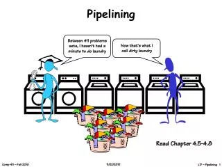
Introduction to Pipelining • Pipelining is overlapping of tasks to realize improvement in overall performance • Consider 4 sub-tasks making up a major task. Lets consider the example given in your text: wash, dry, iron and fold clothes (W D I F) • Now consider n-students want to do this WDIF operation this weekend. • WDIFWDIFWDIFWDIF • WDIF • WDIF • WDIF • WDIF
Instruction Cycle • Fetch: Fetch instruction from memory • Read: Read registers while decoding the instructions • Execute: Execute the operation or calculate an address • Access Memory: Read memory • Write: Write result to register • Assume each of the above operation takes clock cycle. • Assume read and write to register happen in different halves of the cycle. Now we can overlap register read and write.
Pipelining • Time between instructions in pipelined = time between instructions in non-pipelined / # pipelined stages • We want a balanced set of instructions to realized best performance by pipelining • Lets examine the MIPS instruction pipelining page: 373 • How do we design instruction set for pipelining? • MIPS: • instructions of same length • Only few instruction formats • Memory operands only in load and store • Operands must be aligned in the memory
Life is not simple • It is full of hazards • There are situations in pipelining where the next instruction cannot execute in the following cycle. • These are called hazards and there are three different types. • Structural hazards: instruction fetch and data access of memory • Data hazards: • add $s0,$t0,$t1 • sub $t2,$s0,$t3 • Solution: data forwarding • Control hazards: branch…delayed branch, rearranging instructions • Lets look at some examples
How to address pipeline hazards? • Stalls in the pipeline occur when instructions due to • structural hazards (two instructions needing memory at the same time), • control hazards (branch instruction), and • data hazards (results from an instruction needed as data in another instruction). • Solution 1: Forwarding… need to be made during the design of the datapath • Solution 2: introducing a delay or bubble in the pipeline; this is usually done after load and store; delayed load; • Example:
Rendering Code to Avoid Pipeline Stalls Original code Rearranged code • A = B + E • C = B + F lw $t1,0(t0) lw $t2,4(t0) add $t3, $t1, $t2 sw $t3, 12($t0) lw $t4, 8($t0) add $t5, $t1, $t4 sw $t5,16($t0) • A = B + E • C = B + F lw $t1,0(t0) lw $t2,4(t0) lw $t4, 8($t0) add $t3, $t1, $t2 sw $t3, 12($t0) add $t5, $t1, $t4 sw $t5,16($t0)
Control Hazards • There are benchmark program that are used for evaluating the performance of the hardware called SPEC benchmarks • SPECint2000 is one of them. According to this benchmark 13% of the instructions executed are branch. • After a branch we a nop to stall; 13% of the time one extra cycle is added to the time. • Also the instructions loaded into the pipeline need to flushed if the branch is taken. • Branch prediction is another solution: based on the prediction you may want to stall or prefetch.
Revisit and redesign Datapath • Lets redesign our datapath to allow pipelined execution: • See. Figs., 6.9, 6.10, 6.11…
Issues: how to accommodate more than 1 instruction in the datapath?
Add buffer before each stage • IF/ID buffer : 64 bits • ID/EX buffer : 128 bits • EX/MM buffer : 97 bits : 1 for carry/zero • MM/WB buffer: 64 bits • Fig. 6.9 (without control) • Reason out the size of these pipeline registers • How about load register address in a load instruction? • Add 5 more bits to choose the load register; this extra bits will be in ID/EX, EX/MM, MM/WB • See fig. 6.17
Pipelined execution instruction • Instructions: • lw $t1,20($t2) • sub $t3, $t4, $t5 • add $t6, $t5,$t7 • lw $t8,24($t2) • add $t9,$t10,$t11 • Lets draw the multi-cycle pipeline diagram of five instructions. • Fig,6.19, 6.20, 6.21 • Fig. 6.27 with control line buffers at ID/EX and EX/MM
Pipelined control • Control gets complex • Remember, life is not simple • Consider the sequence given below; lets analyze the data forwarding requirement of these instructions. • sub $t2,$t1,$t3 • and $t12, $t2,$t5 • or $t13,$t6,$t2 • add $t14,$t2,$t2 • sw $t15,100($t2) • Fig. 6.28 • How to solve this dependency problem? Detect dependency and resolve at the hardware level.
Pipelined Hazard Management • Data forwarding: conflict at ALU (EX) input operands; R-type instructions • We examined data forwarding as a solution. • How? • Detect data hazards that can be mitigated by data forwarding (logic functions using data in the buffers) • Forward the data to the ALU from EX/MM and MM/WB buffer to EX • Select the operand to ALU (EX) using the logic in step 1
When forwarding does not work? • How about a register trying to read after a load instruction? • Consider: lw $t2,20($t1) and $t4,$t2,$5 or $t8,$t2,$t6 add $t9,$t4,$t2 slt $t1,$t6,$t7 • Since the dependence between the load and the following instruction (and) goes backward in time, this hazard cannot be covered by forwarding. • Solution: introduce stalls in the pipeline.
How to detect this hazard? • If ( ID/EX.MemRead and ((ID/EX.RegisterRt = IF/ID.RegsiterRs) or (ID/Ex.RegsiterRt = IF/ID.RegsiterRt))) stall the pipeline • If the current instruction at ID/EX is load (i.e. memory read instruction) and if the next is dependent on the register being loaded then stall the pipeline by inserting a NOP. • But how? • By deasserting all nine control signals (setting them all to 0) in the EX, MEM, WB stages, we will create a “do nothing” or nop instruction. See Fig. 6.34, 6.35
Datapath design update (6.36) • Hazard detection unit • Control unit
Branch Hazard: Control hazard • Consider the sequence given below: 40: beq $t1,$t3,28 44: and $t12,$t2,$t5 These are useless if the branch is taken 48: or $t13,$t6,$t2 52: add $t14,$t2,$t2 72: lw $t4,50($t7)
Delayed Branch • Delay the branch by introducing a NOP. • In this case logic can be added that will determine if the branch will be taken. • Accordingly you can fetch from the branch target or from the continuous sequence.
Fill NOP with useful instruction • Compiler can assist in detecting the hazards and in introducing NOPs. • It can also insert useful instruction into NOP to improve performance. • We will look at scheduling branch delay slot. • See Figure 6.40
Branch/ Fetch • Follow a branch with bubble and fill the bubble if possible • Detect if the branch will be taken and fetch from target and make this as one of the choices at the mux to the PC • See figure 6.38
Dynamic Branch Prediction (design this) Branch taken Predict Taken Predict Taken Not taken Taken Not taken Taken Predict not-taken Predict not-taken Taken Not taken Not taken
Pipeline and Exceptions • Detect the exception • When an exception occurs, the pipeline will be flushed and we need to fetch from a predetermined location where exception handlers are located. • This is one more addition to the mux at the input of PC. • Location 80000180 has the exception handler and that is loaded into the PC.