
CCMR – RET 2008
CCMR – RET 2008. Week 1 June 29 to July 3 2008. The Hill Exiting Cascadilla Hall. The Hill on College Ave. The Hill on Campus Road. The Hill on East Ave. The Hill to enter Clarke Hall. Day 1 Monday June 29, 2008. Kevin’s Email:

CCMR – RET 2008
E N D
Presentation Transcript
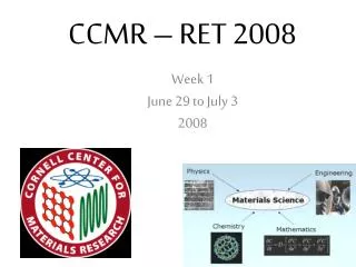
CCMR – RET 2008 Week 1 June 29 to July 3 2008
The Hill Exiting Cascadilla Hall The Hill on College Ave The Hill on Campus Road The Hill on East Ave The Hill to enter Clarke Hall Day 1Monday June 29, 2008 Kevin’s Email: “Cornell is up on a hill so it is extremely steep between the town of Ithaca and Cornell, but the campus itself is relatively manageable. I don’t think it will be too hilly for you...”
The Construction Crane outside of Clarke Hall Our First Detour! We Thought the hard part was over ……
What is Materials Science • Interdisciplinary • Basic Science • Physics • Chemistry • Some biology • Engineering • Electrical • Mechanical • Chemical
As A Materials Scientist What should we ask? • What is the structure and composition of materials? • How are the properties related to its structure and composition? • Can the structure and composition be manipulated through processing to achieve improved properties?
What is Materials Science Used For? • Enables Technologies • Nanotechnology • Information and Telecommunications • Biotechnology • Life science • Energy • Environmental Technology
Atomic Force Microscope • FUNCTION • At Cornell University the scientists are looking at microscopic grooves in the surface of a sample. • In biology, it has been used to look at images of DNA, single proteins, gap junctions, and living cells.(Hon and Hansma, 1992)
Benefits of AFM • It can analyze a sample between 10 and 20 cm2 to a resolution of less than 2 nanometers. • It is considered a non-destructive method of scanning because the force used by the probe is very small. • There is very little time needed for preparation.
Problems With AFM • It is difficult to use with biological structures because they are soft and can be distorted or destroyed. • Hoh and Hansma, 1992, Trends Cell Bio 2, 208-213
Classroom Uses • Princeton RET 1999- Lesson plan had the students construct and test a model of an AFN over five periods. • Stanford Nanofabrication Facility-Nanoleap program-physics module- Their remote access activity uses AFM. Live video is beamed to high school classes.
How the AFM Works • The AFM has a fine ceramic or semiconductor tip that acts like the needle in a phonograph. The tip is at the end of a canilever. As the tip is repelled or attracted by the surface, the canilever beam deflects. The magnitude of the deflection is caught by a laser. This gives the topography of the sample.
Water Jet Cutting Water jet cutting is done using a garnet abrasive. Low psi of 15,000 High psi of 50,000
Water Jet Cutting Water jet cutting is done using a garnet abrasive. Low psi of 15,000 High psi of 50,000
Planar Magnetron Sputtering • Deposits thin metal and insulation films onto substrates • Material does not need to be heated • More than one material can be sputtered at a time
Planar Magnetron Sputtering Center Magnet Cathode Ring Magnet Target (used) Target Mount
Planar Magnetron Sputtering • The chamber is evacuated • Argon is introduced, • then ionized in the • chamber Argon Plasma
Planar Magnetron Sputtering • The cathode ring behind the target attracts the argon ions • The ions bombard the target, knocking off atoms, creating an atomic “dust”. • The dust settles on the substrate • Thickness of the deposition is monitored by crystal sensors
Planar Magnetron Sputtering We used this machine to: Deposit Niobium and Tin onto four sapphire substrates in a 2:1 ratio Two of the samples were heated to 1000°C for 5 hours to anneal the metals We will be testing the different properties of these samples in the weeks to come Coated samples in the furnace Furnace used to anneal metals
Planar Magnetron Sputtering We used this machine to: Coat 2” silicon wafers with gold. The metal disks made with the water jet cutter were used as masks.
Instron Model 1125 • Electro-mechanical • Records force & distance
* Calibration “strain gauge” * 6 Samples * What it Means * Video * Results
* Calibration “strain gauge” * 6 Samples * What it Means * Video * Results STEEL DELRIM COPPER BRASS ALUMINUM TITANIUM
* Calibration “strain gauge” * 6 Samples * What it Means * Video * Results FORCE DISTANCE STRETCHED
* Calibration “strain gauge” * 6 Samples * What it Means * Video * Results FORCE DISTANCE STRETCHED
* Calibration “strain gauge” * 6 Samples * What it Means * Video * Results FORCE DISTANCE STRETCHED
* Calibration “strain gauge” * 6 Samples * What it Means * Video * Results FORCE DISTANCE STRETCHED
* Calibration “strain gauge” * 6 Samples * What it Means * Video * Results
* Calibration “strain gauge” * 6 Samples * What it Means * Video * Results