Download
1 / 16
190 likes | 420 Views
Magnetic Circuits and Transformers. Discussion D10.1 Chapter 6. Hans Christian Oersted (1777 – 1851). X. 1822. In 1820 he showed that a current produces a magnetic field. Ref: http://chem.ch.huji.ac.il/~eugeniik/history/oersted.htm. André-Marie Ampère (1775 – 1836).

E N D
Magnetic Circuits and Transformers Discussion D10.1 Chapter 6
Hans Christian Oersted (1777 – 1851) X 1822 In 1820 he showed that a current produces a magnetic field. Ref: http://chem.ch.huji.ac.il/~eugeniik/history/oersted.htm
André-Marie Ampère (1775 – 1836) French mathematics professor who only a week after learning of Oersted’s discoveries in Sept. 1820 demonstrated that parallel wires carrying currents attract and repel each other. attract A moving charge of 1 coulomb per second is a current of 1 ampere (amp). repel
Michael Faraday (1791 – 1867) Self-taught English chemist and physicist discovered electromagnetic induction in 1831 by which a changing magnetic field induces an electric field. A capacitance of 1 coulomb per volt is called a farad (F) Faraday’s electromagnetic induction ring
Joseph Henry (1797 – 1878) American scientist, Princeton University professor, and first Secretary of the Smithsonian Institution. Built the largest electromagnets of his day Discovered self-induction Unit of inductance, L, is the “Henry”
Magnetic Fields and Circuits A current i through a coil produces a magnetic flux, f, in webers, Wb. B = magnetic flux density in Wb/m2. H = magnetic field intensity in A/m. m = magnetic permeability Ampere's Law: reluctance Magnetomotive force
Magnetic Flux Current entering "dots" produce fluxes that add. Magnetic flux, f, in webers, Wb.
i Faraday's Law Total flux linking coil 1: Faraday's Law: induced voltage in coil 1 is Sign of induced voltage v1 is such that the current i through an external resistor would be opposite to the current i1 that produces the flux f1. Symbol L of inductance from Lenz Example of Lenz's law
Mutual Inductance Faraday's Law In linear range, flux is proportional to current mutual inductance self-inductance
Mutual Inductance Linear media Let
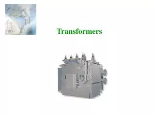
Ideal Transformer - Voltage The input AC voltage, v1, produces a flux f This changing flux through coil 2 induces a voltage, v2 across coil 2
Ideal Transformer - Current Magnetomotive force, mmf f The total mmf applied to core is For ideal transformer, the reluctance R is zero.
Ideal Transformer - Impedance Load impedance Input impedance Turns ratio
Ideal Transformer - Power Power delivered to primary Power delivered to load Power delivered to an ideal transformer by the source is transferred to the load.
L.V.D.T. Linear Variable Differential Transformer Position transducer http://www.rdpelectronics.com/displacement/lvdt/lvdt-principles.htm http://www.efunda.com/DesignStandards/sensors/lvdt/lvdt_theory.cfm
LVDT's are often used on clutch actuation and for monitoring brake disc wear LVDT's are also used for sensors in an automotive active suspension system