Download
1 / 47
470 likes | 688 Views
ECE 4100/6100 Advanced Computer Architecture Lecture 7 Dynamic Scheduling (I). Prof. Hsien-Hsin Sean Lee School of Electrical and Computer Engineering Georgia Institute of Technology. i1. i2. i5. i6. i7. i10. i11. i12. i3. i8. i13. i4. i9. i14. i15. i16. Data Flow Graph (DFG).

E N D
ECE 4100/6100Advanced Computer ArchitectureLecture 7 Dynamic Scheduling (I) Prof. Hsien-Hsin Sean Lee School of Electrical and Computer Engineering Georgia Institute of Technology
i1 i2 i5 i6 i7 i10 i11 i12 i3 i8 i13 i4 i9 i14 i15 i16 Data Flow Graph (DFG) i1: r2 = 4(r22) i2: r10 = 4(r25) i3: r10 = r2 + r10 i4: 4(r26) = r10 i5: r14 = 8(r27) i6: r6 = (r22) i7: r5 = (r23) i8: r5 = r6 – r5 i9: r4 = r14 * r5 i10: r15 = 12(r27) i11: r7 = 4(r22) i12: r8 = 4(r23) i13: r8 = r7 – r8 i14: r8 = r15* r8 i15: r8 = r4 – r8 i16: (r28) = r8 Data Flow Graph (or Data Dependency Graph)
Data Flow Execution Model • To exploit maximal ILP • An instruction can be executed immediately after • All source operands are ready • Execution unit available • Destination is ready (to be written)
Dynamic Scheduling • Exploit ILP at run-time • Execute instructions out-of-order by a restricted data flow execution model (still use PC!) • Hardware will • Maintain true dependency (data flow manner) • Maintain exception behavior • Find ILP within an Instruction Window (pool) • Need an accurate branch predictor • Pros • Scalable performance: allows code to be compiled on one platform, but also run efficiently on another • Handle cases where dependency is unknown at compile-time • Cons • Hardware complexity (main argument from the VLIW/EPIC camp)
i1 i2 i5 i6 i7 i10 i11 i12 i3 i8 i13 i4 i9 i14 i15 i16 Out-of-Order Execution i1: r2 = 4(r22) i2: r10 = 4(r25) i3: r10 = r2 + r10 i4: 4(r26) = r10 i5: r14 = 8(r27) i6: r6 = (r22) i7: r5 = (r23) i8: r5 = r6 – r5 i9: r4 = r14 * r5 i10: r15 = 12(r27) i11: r7 = 4(r22) i12: r8 = 4(r23) i13: r8 = r7 – r8 i14: r8 = r15* r8 i15: r8 = r4 – r8 i16: (r28) = r8
OOO Execution • OOO execution out-of-order completion • OOO execution out-of-order retirement (commit) • No (speculative) instruction allowed to retire until it is confirmed on the right path • Fetch, decode, issue (i.e., front-end) are still done in the program order
CDC 6600 Scoreboard Algorithm • Enable OOO Execution to address long-latency FP instructions • Use scoreboard tables to track • Functional unit status • Register update status • Issue and execute instructions whenever • No structural hazard • No data hazard • Cons • Stop issue when WAW is detected • Stop writeback when WAR is detected
FP Mult FP Mult Data bus FP Divide Functional Units Registers Data bus FP Add Data bus Integer Data bus SCOREBOARD Memory Fu Busy Op Dest Src1 Src2 Dep1 Dep2 Control bus/Status Int 1 Load F1 R3 Mult1 1 Mult F0 F1 F4 Int FU Status Table Mult2 0 Add 1 Sub F8 F6 F1 Int F0 F1 F2 .. .. .. F31 Div 1 Div F2 F0 F6 Mult1 FU Mult1 Int Div .. .. .. xxx Register Update Table CDC6600 Scoreboard
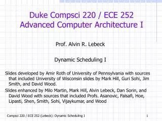
IBM 360 • IBM 360 introduced • 8-bit = 1 byte • 32-bit = 1 word • Byte-addressable memory • Differentiate an “architecture” from an “implementation” • IBM 360/91 FPU about 3 years after CDC 6600 (1966-7) • Tomasulo algorithm • Dynamic scheduling • Register renaming
Tomasulo Algorithm • Goal: High Performance without special compilers • Dynamic scheduling done completely by HW • We generally use “supercalar processor” for such category as opposed to “VLIW” or “EPIC” • Differences between IBM 360 and CDC 6600 ISA • IBM has only 2 register specifiers per inst vs. 3 in CDC 6600 • Make WAW and WAR much worse • IBM has 4 FP registers vs. 8 in CDC 6600 • Smaller number of architectural register, compiler is incapable of exploiting better register allocation • IBM has memory-to-register operations • Why study? Lead to Pentium Pro/II/III/4, Core, Alpha 21264, MIPS R10000, HP 8000, PowerPC 604
IBM 360/91 FPU w/ Tomasulo Algorithm • To not stall floating point instructions due to long latency • Two function units FP Add + FP Mult/Div • 360/91 FPU is not pipelined • Three new Mechanisms • Reservation Stations (RS) • 3 in FP Add, 2 in FP mult/div • Register name is discarded when issue to reservation station • Tags • 4-bit tag for one of the 11 possible sources (5 RSs + 6 FLB for loads) • Written for unavailable sources whose results are being generated by one of the sources (5 RS or 6 FLB) • New tag assignment eliminates false dependency • Common Data Bus (CDB), driven by • 11 Sources: 5 RS + 6 FLB • 17 Destinations: 2*5 RS + 3 SDB + 4 FLR
Basic Principles • Do not rely on a centralized register file ! • RS fetches and buffers an operand as soon as it is available via CDB • Eliminating the need to get it from a register (No WAR) • Data Flow execution model • Pending instructions designate the RS that will provide their input (renaming and maintain RAW) • Due to in-order issue, the register status table always keeps the latest write (No WAW issue)
Key Representation • Op Operation to perform in the units • Vj Value of Source 1 (called SINK in 360/91) • Vk Value of Source 2 (called SOURCE in 360/91) • Qj The RS (tag) will produce source 1 • Qk The RS (tag) will produce source 2 • A(ddress) Hold info for the memory address generation for a load or store • Qi Whose value should be stored into the register
IBM 360/91 FPU w/ Tomasulo Algorithm FP operation stack (FLOS) FP Registers (FLR) From Mem FP Load Buffers (FLB) 6 5 4 3 2 1 Store Data Buffers (SDB) 3 2 1 2 1 Reservation Stations To Mem FP Adder FP Mult/Div Common Data Bus (CDB)
Control Control Tag (Qi) Tag Control Control Sink (Vj) Source (Vk) Tag (Qj) Tag (Qk) IBM 360/91 FPU w/ Tomasulo Algorithm Tags in FLB FP operation stack (FLOS) From Mem FLB 6 5 4 3 2 1 FLR Tags and other info in RS 3 2 1 Store Data Buffers (SDB) 2 1 Reservation Stations To Mem FP Adder FP Mult/Div Common Data Bus (CDB)
RAW Example: i: R2 R0 + R4 (2 clks) j: R8 R0 + R2 (2 clks) Cycle #0: Cycle #1: Issue i Cycle #2: Issue j
RAW Example: i: R2 R0 + R4 (2 clks) j: R8 R0 + R2 (2 clks) Cycle #3: Broadcasts tag and result: CDB_a=<RS1,16.0> Cycle #5: Broadcasts tag and result: CDB_a=<RS2,22.0>
WAR Example: i: R4 R0 x R8 (3) j: R0 R4 x R2 (3) k: R2 R2 + R8 (2) Cycle #0: Cycle #1: Issue i Cycle #2: Issue j
WAR Example: i: R4 R0 x R8 (3) j: R0 R4 x R2 (3) k: R2 R2 + R8 (2) Cycle #3: Issue k Cycle #4: Broadcasts CDB_m=<RS4,46.8>; Cycle #5: Broadcasts CDB_a=<RS1,11.3>
WAR Example: i: R4 R0 x R8 (3) j: R0 R4 x R2 (3) k: R2 R2 + R8 (2) Cycle #7: Broadcasts CDB_m=<RS5,163.8>
WAW Example: i: R4 R0 x R8 (3) j: R2 R0 + R4 (2) k: R4 R0 + R8 (2) Cycle #0: Cycle #1: Issue i Cycle #2: Issue j
WAW Example: i: R4 R0 x R8 (3) j: R2 R0 + R4 (2) k: R4 R0 + R8 (2) Cycle #3: Issue k Cycle #4: Broadcasts CDB_m=<RS4,46.8> Cycle #5: Broadcasts CDB_a=<RS2,13.8>
WAW Example: i: R4 R0 x R8 (3) j: R2 R0 + R4 (2) k: R4 R0 + R8 (2) Cycle #6: Broadcasts CDB_a=<RS1,52.8>
These are RS, we have only one FU for each type (MUL, ADD, LD). We reduce Load from 6 to 3 for simplicity. SDB is not shown either Tomasulo Example (H&P Text)
Assumption • INT (load) 1 cycle • MULT 10 cycles • ADD 2 cycles • DIVIDE 40 cycles
Tomasulo Example Cycle 2 Note: Unlike CDC6600, RS enables multiple outstanding loads Load is calculating the effective address
Tomasulo Example Cycle 3 • Note: registers names are removed (“renamed”) in Reservation Stations; MULT issued vs. scoreboard • Load1 completing; what is waiting for Load1?
Tomasulo Example Cycle 4 • Load1 write to CDB; Load2 completing; what is waiting for Load2?
Tomasulo Example Cycle 6 • R(F6) was entered in Cycle 5 • Issue ADDD here vs. scoreboard?
Tomasulo Example Cycle 7 • Add1 completing; what is waiting for it?
Tomasulo Example Cycle 10 • Add2 completing; what is waiting for it?
Tomasulo Example Cycle 11 • Write result of ADDD here vs. scoreboard? • All quick instructions complete in this cycle!
Tomasulo Example Cycle 56 • Mult2 is completing; what is waiting for it?
Tomasulo Example Cycle 57 • Once again: In-order issue, out-of-order execution and completion.
Compare to Scoreboard Cycle 62 • Why take longer on scoreboard/6600? • Structural Hazards • Lack of forwarding
Issues in Tomasulo Algorithm • CDB at high speed? • Precise exception issues • Speculative instructions • Branch prediction enlarges instruction window • How to rollback when mispredicted?