GlueX Experiment Front-End Digitization Electronics Overview
10 likes | 107 Views
The GlueX experiment features fully pipelined custom electronics digitization for wire-bonded Gas Die, utilizing Flash ADCs and F1TDCs for various detectors. The memory ring buffer can hold 3ms of data, eliminating expensive delay cables. The Level 1 trigger system digitally sums calorimeter channels every 4 ns for fast processing. The GTP integrates signals for the final trigger stage, incorporating drift chambers. Various modules manage trigger systems and signal distribution for precise synchronization.

GlueX Experiment Front-End Digitization Electronics Overview
E N D
Presentation Transcript
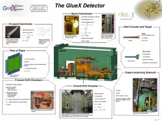
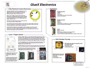
CHL-2 GlueX Electronics ~ 4 mm Fully Pipelined Custom Electronics Digitization Wire-bonds (Au) GAS-1 Die (0.25 μm CMOS) Lead-frame (QFN 64 9x9 mm) The GlueX experiment will utilize fully pipelined front end digitization electronics. This means that the detector signals will be continuously digitized in the front end boards, storing the values in on-board memory. When a Level 1 trigger is received, the board will look back in time to the appropriate memory location and apply an FPGA-based algorithm. This will integrate the signal in a fixed time window as well as fit the leading edge of any signal to obtain the time. Eventually, the integral and time values will be transported off the board through the VME backplane. • 125 MHz Flash ADC • 125 Msps • 12 bits • 72 channels • VXS connection for clock synchronization • Used for Drift chambers • 250 MHz Flash ADC • 250 Msps • 12 bits • 16channels • VXS connection for digital sum (L1 trigger) and clock synchronization • Used for calorimeters and scintillators Memory ring buffer The ring buffers used to hold the samples for each channel are large enough to contain the last 3ms of sample data. This eliminates the need for the long, expensive delay cables used in previous generations of Nuclear Physics experiments. Certain flash ADC modules are also equipped to sum the samples over all channels and transmit the sum via VXS (a high speed point to point connection system) to a central module to be used in the L1 trigger. A total digital sum of an entire 2800 channel calorimeter can therefore be update every 4ns. (See below) • F1TDC • 60ps or 115ps LSB • 12 bits • 32 or 48 channels (depends on desired resolution) • VXS connection for clock synchronization • Used for Fast detectors (60ps mode) and Drift chambers (115ps mode) Level 1 Trigger System The level 1 trigger system (L1) will include both partial and total sums of the calorimeters. The >3500 calorimeter channels will be digitally summed every 4 ns and a threshold applied. This is done starting at the Flash ADC module level by summing all channels in the module and sending the sum over a high speed VXS connection to a dedicated Crate Trigger Processor (CTP) module. The CTP will digitally sum the signals from all of the flash ADC modules in the crate and send the 32bit value over a high speed optical connection to a SubSystem Processor (SSP) module. The SSP modules will each create a sum of the inputs from several crates and pass it over a VXS connection to the Global Trigger Processor (GTP) module. Drift Chamber Pre-amp ASIC chip GPC-II 24 channel Pre-amp Card • ASIC (Application Specific Integrated Circuit) • Pre-amplifier and shaper • Discriminator mode • 8 channels per chip • Custom design for GlueX The GTP will create the final stage sum as well as include signals from the Tagger and Time Of Flight (TOF) detectors to form the Level 1 trigger. Illustration of the Level 1 trigger system A Trigger Supervisor (TS) module manages the L1 trigger and communication with all of the crates. A Trigger Interface(TI) board and Signal Distribution(SD) board are used to distribute trigger and clock synchronization information to all of the modules in a crate. • GPC-II (GlueX Pre-amp Card) • 3 ASIC chips (one underneath) • 24 channels • Drift Chambers • Custom design for GlueX Performance of the shaper circuit in the ASIC input output input output SD: Signal Distribution module CTP: Crate Trigger Processor module DIS2011 tour: April13, 2011 D. Lawrence