Download
1 / 29
290 likes | 427 Views
SCT Hybrids and Modules - Carl Haber(LBNL). 1.1.2.2 SCT Hybrids 1.1.2.2.1 Design 1.1.2.2.2 Prototypes 1.1.2.2.3 Production 1.1.2.3 SCT Modules 1.1.2.3.1 Design 1.1.2.3.2 Prototypes 1.1.2.3.3 Production. US SCT Group. Hybrids and Modules Responsibilities

E N D
SCT Hybrids and Modules - Carl Haber(LBNL) • 1.1.2.2 SCT Hybrids • 1.1.2.2.1 Design • 1.1.2.2.2 Prototypes • 1.1.2.2.3 Production • 1.1.2.3 SCT Modules • 1.1.2.3.1 Design • 1.1.2.3.2 Prototypes • 1.1.2.3.3 Production
US SCT Group • Hybrids and Modules Responsibilities • Lawrence Berkeley National Laboratory • >Prototyping activities • >Assembly and test of hybrids • >Assembly and test of modules • >Development of module assembly setup • University of California, Santa Cruz, SCIPP • >Prototyping activities • >Assembly and test of hybrids • >Hybrid and module rework and repair
Semiconductor Tracker(SCT) • Lots of silicon • ~60 m2 • ~6 million channels • Single-sided, p-on-n detectors bonded back-to-back to provide small angle stereo => modules • Radiation environment is about 10M Rad worst case over lifetime. • US has concentrated on electronics and module construction.
Silicon Strip IC Electronics • The ATLAS signal processing scheme for silicon strips is based upon a binary hit/no-hit readout • This approach was pioneered in the US originally for SDC and Zeus.. • Eventually two rad-hard solutions came under development • CAFÉ-M(bipolar from Maxim) + ABC(CMOS from Honeywell) - 2 chips.. • ABCD(BiCMOS from Temic) - 1 chip. • ABCD design chosen and under final development
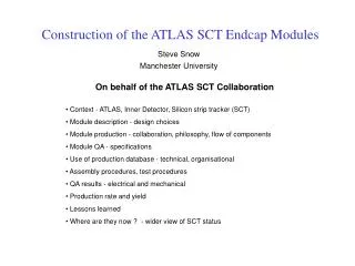
SCT Module Wire bonds Front-end ICs Strip detector Hybrid • Modules are the building blocks of the SCT system • Each module consists of: • 4 single sided detectors, p implant in n type material, 500 V operation, 768 strips per side, 128 mm • Thermal baseboard of pyrolytic graphite with BeO side facings • Hybrid holding 12 ABCD chips • 4608 high density bonds • US to deliver 670 modules
Completed assembly areas Strips assembly area showing vision assisted alignment station Pixel assembly area with gluing machine visable
1.1.2.2.1 Hybrid Design • The US group contributed to the hybrid design since 1995, developing the basic layout, interconnectivity, and schematic • The US group executed a series of designs based upon high thermal conductivity ceramic (AlN and BeO) substrates (following on work for CDF) • In 2000 Atlas chose a hybrid techology based upon copper/kapton flexible circuits developed by the KEK group. Cost was the primary driver. • The US group no longer has design responsibility but continues to contribute to technical reviews and specifications for these parts.
1.1.2.2.2 Hybrid Prototypes • The US Group fabricated a series of prototypes in the ceramic technology 1995 -1999 • These were used extensively in bench and beam tests, irradiations, and to validate the readout chips • The chosen Kapton design is fabricated in Japan. • Prototype samples have been distributed around the collaboration for tests and validation. • Initial concerns were for etch and surface quality and seem to have been solved in most recent batch. • We are in the process of studying these units. • Noise, stability, and interference are issues still to be fully demostrated when FE chips are integrated into the hybrid/modules but present results look good. • Deadtimeless operation tests recently begun
1.1.2.2.3 Hybrid Production • Hybrids with discrete components mounted will be supplied by Japan • US is to attach tested ABCD chips and wirebond • Plan to to bond 2 hybrids in an 8 hour shift • Bonding capacity and expertise in place at LBL and UCSC. Use of local industry also an option • LBL bonder recently modified to clear components on Kapton hybrid, tested sucessfully in auto mode. • First production level test system installed and commissioned at LBL, additional systems ordered. • Comprehensive test protocols are under discussion and review within. • Burn-in process still to be fully specified
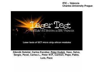
Barrel Silicon Strip Modules Double-sided dummy module • Tooling for large-scale production(we have to assemble 670 modules)
Module build process • Modules will be built using a semi-automatic process to avoid operator error and control uniformity • The same process will be used by a sub-set of the SCT module assembly sites • The process is based upon precision stages driven by stepper motors, optical monitoring with pattern recognition of fiducials on detectors, and precision fixtures • The plan is to build 2 modules/8 hour shift • Module build rate is also effected by delivery of components from non-US sites (baseboards, hybrids, wafer fabrication, detectors)
1.1.2.3.1 Module Design • The US groups have been involved in the design of the module since 1995. • Significant involvement in hybrid/electrical interaction issues. Validated bridged construction concept. • Collaboration with RAL on module assembly process • Design of various assembly and bonding fixtures for use in the construction of prototype and production build (example: hybrid folding fixture) • Development of build specification • Organization of working group on module assembly process.
1.1.2.3.2 Module Prototypes • Prototyping activities since 1995. Developed an early assembly process used for test beam module builds. • Began to install production design system for assembly in 1998 following work of RAL group. • V1 of that system tested in 1998 • In process of commissioning V2 consisting of new fixtures and new software • Metrology based upon SmartScope tool. New fixture in hand and being tested. • Module TDR in late May 2001. Plan is to show results on modules built with V2 system at TDR
Module assembly process • Components are 4 detectors, baseboard with glue applied, tested hybrid. • Build system follows programmed sequence, twice per day • Load a pair of detectors on stages • Drive to approximate position of detector fiducials • Optics performs pattern recognition on fiducials and moves detectors into proper alignment • Detector pair lifted with vacuum plate. • Process repeated on second pair • Baseboard glue pattern applied with gluing robot • Baseboard mounted in "window frame" fixture • Vacuum plates engaged into frame with precision pins and linear bearings • Glue cures at room temperature • Metrology checked • Hybrid folded and glued around detector sandwich • Wirebonding performed • Test, rework, burn-in
1.1.2.3.3 Module Production • Build system will be used in production • Assuming FDR is passed, plan is to use present fixtures, mechanics, and software in production build • Clean space adequate and ready • Database software in hand, needs to be loaded and understood. • Expect to be ready for delivery of first production components in Fall 2001.
Manpower and Time • Plan is to build 2 hybrids per day • Wirebonding rate from tests and from CDF experience predicts that this is comfortable. One technician required • Sufficient electronics for test and burn-in on order. • Testing by physicists and students. • Plan is to build 2 modules per day • Module build process has been timed in the UK and evaluated here. Slowest step is glue cure and multiple fixtures will be available. One senior and one junior technician planned for • Wirebonding rates as for hybrids. Plan for second shift, one technician required. • Sufficient electronics for test and burn-in on order. • Testing by physicists and students. • Two technicians experienced in bonding in place, one senior technician in place, one junior required.
Conclusions • Most of tooling and process for hybrid and module assembly in place at US sites • Production system being commissioned • Good experience base exists • Time for processes has been calibrated on practice runs and from previous projects • Plan to be ready for components in Fall of 2001