Download
1 / 37
370 likes | 533 Views
Electricity Circuits 2 Simple Circuit Analysis. Introductory Notes. 2 A. = 2C/s. Facts About Our Circuit Model. C. +. –. Batteries have a positive and negative terminal. How do we label the terminals of the battery in the circuit opposite?

E N D
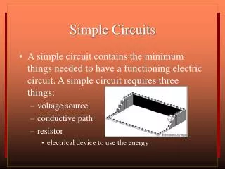
2 A = 2C/s Facts About Our Circuit Model C + – • Batteries have a positive and negative terminal. How do we label the terminals of the battery in the circuit opposite? The long line is the positive and the short fat line is the negative. • Batteries will cause an electric current to flow around a circuit if it has a fully connected path to follow. What direction will an electric current flow in the circuit opposite? Electric current flows from positive to negative. • Electric current is the movement of charge around a circuit and represents the number of charges per second passing through each component in the circuit? Instead of talking about individual charges in an electric current we use a special unit called Coulombs . Why do we need this special unit and what does it mean? Because a typical current represents millions of millions of millions of charges per second it is much easier to talk about “groups” of charge called Coulombs and represent current as Coulombs per second. 1 Coulomb is just over 6 million millionmillion individual charges • Electric currents are measured in amps which represents the number of Coulombs per second passing through each part of the circuit. What does it mean if a current of 2 amps is measured in the circuit opposite? There are 2 Coulombs of charge flowing through the battery and resistor every second. 12V
Part A: Analysis Without FormulaeQuestion 1 A 9.0V battery gives 9J of energy to each coulomb that passes through it ? 9V 0J 9J G1 G2
V V Q2a Fill in the virtual energiesand the ammeter and voltmeter readings in the circuit below. V = voltage increase 6V V V = voltage drop + Energy 6J 6J 6J 6J 0J 0J 0J 0J 0J 6J A2 A1 0J 6J Different Resistances 0J 6J 4 A 4A ? 0J 6J R1 R2 6J 6J 0J 2J 2J 0J 2J 4V 2V
V V Q2b Fill in the virtual energiesand the ammeter and voltmeter readings in the circuit below. V = voltage increase 8V V V = voltage drop + Energy 8J 8J 8J 8J 0J 0J 0J 0J 0J 8J A2 A1 0J 8J Different Resistances 0J 8J 3 A 3A ? 0J 8J R1 R2 8J 8J 0J 3J 3J 0J 3J 5V 3V
Part A: Analysis Without FormulaeQuestion 3 State the potential difference from the battery configurations below: Vout = 12V Vout = 6V ? ?
V V Q4 Fill in the virtual energiesand the voltmeterreadings in the circuit below. V = voltage increase ?V V = voltage drop 18V 9V 9V 9J 0J 18J 9J ?V 0V THESE ARE identical Globes 0V ?V G2 G3 G1 6J 12J 18J 0J 6V 12V
Part A: Analysis Without Formulae ????? 5.The unit used to measure electric charge in circuits is called the Coulomb 6. A current of 3.0A through a battery means that 3.0 C of charge passes through the battery each second 7. If 2.0A flows through a resistor for 5.0 seconds, then 10C of charge would have passed through the resistor 8. If 18C of charge passed through a resistor in 3.0seconds then the current through the resistor is 6.0 A ?? ?? ??
Part A: Analysis Without FormulaeQuestion 9 State whether the globes in the circuits below are in series or in parallel. Parallel Parallel Series
Part A: Analysis Without FormulaeQuestion 10 In the circuit below the currents in ammeter 2 and ammeter 4 are A2=2.0A and A4 =5.0A. • A3 = 2.0 A • A1 = 3.0 A ?? ?? 3A 5A 2A
V V V Part A: Analysis Without FormulaeQuestion 11 In the circuit below the potential difference across B and C (VBC) = 4.0V. • Each coulomb passing through the battery drains 15 J of energy from it. • Each coulomb passing through R1 gives off 4.0 J of energy. • VAB= 0 V • VCD= 11 V 11V 0V 4V ?? ?? ?? ??
Part A: Analysis Without FormulaeQuestion 12 If the variable resistance below is increased • The reading on V1 will increase. • The reading on V2will decrease. ?? ??
Question 13 (a) When only switch 1 is closed globes 1 and 2 would be on. ?? (b) If switch 1 is shut and then switch 2 is closed globe 1 will go out and globe 2 will get brighter. ?? ?? Short circuiting occurs when a very low resistance path is put across a component. In such circumstances the current is diverted away from the component that has been short circuited. Because the short circuited components have essentially been removed from the circuit the overall resistance will have decreased and hence the current will increase.
Part A: Analysis Without FormulaeQuestion 14 For the Circuit: (a)When the switch is open an observer would notice that all the globes would be on. (b)When the switch is shut the changes observed would be that. globe 1 will get brighter globe 2 will go out globe 3 will go out ?? ?? ?? ??
Part A: Analysis Without FormulaeQuestion 15 (a) Use a red pen to show how to connect a wire to make globes 3 and 4 go out. (b)When this wire is connected globes 1, 2 and 5 will get brighter ??
Question 16 The symbol in the diagrams below represents a fuse which is designed to blow out if there is too much current flowing through it. Circuit 1 Circuit 2 Circuit 3 A A X X X With the resistance out of the circuit there will be a high current and the ammeter could be damaged. With the resistance out of the circuit there will be a high current but the fuse will blow protecting the ammeter. No current will flow through the ammeter it is safe. Y Y Y A (a) Which circuit(s) could damage the ammeter if there was a short circuit from X to Y. Circuit 1
Question 16 The symbol in the diagrams below represents a fuse which is designed to blow out if there is too much current flowing through it. Circuit 1 Circuit 2 Circuit 3 A A X X X With the resistance out of the circuit there will be a high current and the ammeter could be damaged. With the resistance out of the circuit there will be a high current but the fuse will blow protecting the ammeter. No current will flow through the ammeter it is safe. Y Y Y A (b) Which circuit will protect the ammeter by having the fuse blow out if there was a short circuit from X to Y. Circuit 3
Part A: Analysis Without FormulaeQuestion 17 The heater in an electric hot water service has two switch sensors, one which goes on when there is enough water in the heater and one which goes on when the water is below a certain temperature. The heater only goes on when both switches are on. Using a battery, two switches and a light, design a model of a hot water circuit that turns on a light only when both switches are on. S1 S2 OFF ON
Part A: Analysis Without FormulaeQuestion 18 The alarm in a burglar system has two switch sensors, and when either switch detects an intruder the alarm goes off. Using a battery, two switches and a light, design a model of a burglar alarm that turns a light on when either of the switches is turned on. S2 S1 OFF ON
Ohm’s Law • In 1827 Georg Ohm published his experimental results that the electric current (I) in a circuit depends on the Voltage (V) of a battery and the Electrical Resistance (R) in a Circuit? What rule did he find for electric current and what name is it given? The rule is I and it is called Ohm’s Law. • What is the meaning and units of the symbols in Ohm’s Law? ?? ?? ?? ?? ?? ?? ?? ??
Ohm’s Law 3 C/s 6 C/s C I = ? V = 12V R = 2.0 I I I = 6.0A + • What electrical current will flow in the circuit? • What does the current in the previous question actually mean? There are 6 Coulombs of charge flowing through the circuit every second • Work out in your head the current that would flow if another 2.0 resistor was added to the circuit in question 3 as shown above? using I in your head I = 3Amps – 3.0A 6.0A 2Ω 12V 2Ω
Ohm’s Law • Ohm’s Law can be written in three forms and each rule can be worked out from the triangle below. What are the 3 rules? V= IR I R Ohm’s Law V I R
A Quirk In History 2 C/s ? C + • How many coulombs of charge are flowing through the battery every second in the circuit opposite ? Current = 2.0A so 2 coulombs per second • What particles are REALLY being driven around the circuit by the battery? electrons • What does a Coulomb represent when talking about current in an electric wire? 1 Coulomb = 6.25 1018electrons. • What direction are the electrons flowing? Since electrons have a negative charge they actually flow from negative to positive. THE OPPOSITE DIRECTION TO THE CURRENT!!!!! • Why is there a contradiction between the direction of the current and the actual direction of charge flow? – e– 2.0A 2Ω e– Ohm’s Law 18V 7Ω V I R I = ? V = 18V R = 9.0 I I I = 2.0A Physicists wrote the direction of the current into circuit theory before they knew the existence of electrons. By that time the current direction was too entrenched in theory.
V IR Ohm’s Law & The Power Formulae V = IR V = Voltage or Potential Difference (measured in Volts- V) = J/C gained by a Coulomb passing through a battery OR J/C lost from a Coulomb passing through a resistor or device I = Electrical Current (measured in Amps- A) = C/s passing through a device R = Resistance (measured in Ohms- ) = opposition to electrical current flow P = Power (measured in Watts- W) = J/s dissapated in a device = J/s drain on a battery I = R = P = VI = I2R = =
V IR Working With Ohm’s LawQuestion 1 (a) What will be the electrical potential difference of the battery in the circuit below? V = ? I = 0.20A R = 10 V = IR V = 0.2 10 V = 2.0V P = VI = I2R = =
V IR Working With Ohm’s LawQuestion 1 (b) What will be the power dissapated in the resistor below? P = ? I = 0.20A R = 10 P = I2R P = 0.22 10 P = 0.40 W P = VI = I2R = =
V IR Working With Ohm’s LawQuestion 2 (a) What will be the electrical resistance of the resistor in the circuit below? R = ? V = 9.0V I = 0.10A R R R = 90 P = VI = I2R = =
V IR Working With Ohm’s LawQuestion 2 (b) What will be power drain on the battery below? P = ? V = 9.0V I = 0.10A P = VI P = 9 0.1 R = 0.90W P = VI = I2R = =
V IR Working With Ohm’s LawQuestion 3 (a) What will be the electrical current flowing through the circuit below? I = ? V = 12V R = 20 I = 0.60A P = VI = I2R = =
V IR Working With Ohm’s LawQuestion 3 (b) What will be the power dissipated in the resistor below? P = ? V = 12V R = 20 P P P= 7.2W P = VI = I2R = =
V IR Working With Ohm’s LawQuestion 4 For the circuit. • Total resistance = • Work out the total current 150 I = ? V = 12V R = 150 I = 0.080A P = VI = I2R = =
V IR Working With Ohm’s LawQuestion 4 0.080A For the circuit. c) Work out V50 V = ? I = 0.080A R = 50 V = IR V = 0.08 50 V = 4.0V P = VI = I2R = =