Download
1 / 27
280 likes | 507 Views
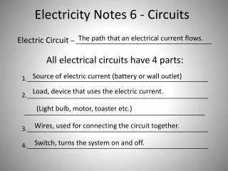
Electricity and Circuits. Developed by Dr. Rhett Davis (NCSU) and Shodor. What Do Engineers Do?. Study the forces of nature Apply them to do useful things Example: Water Wheel What are the forces? How is it useful?. Water Wheels. Water-wheels are Mechanical Engineering

E N D
Electricity and Circuits Developed by Dr. Rhett Davis (NCSU) and Shodor
What Do Engineers Do? • Study the forces of nature • Apply them to do useful things • Example:Water Wheel • What are the forces? • How is it useful?
Water Wheels • Water-wheels are Mechanical Engineering • Today, we’ll look at Electrical Engineering = +
What do you need to make a Water Wheel Work? • Water – Makes everything work • River – Source of flowing water • Pipes – To direct the water where you want it to go and regulate the flow • Wheel – To convert the force of the flowing water into force to grind the wheat
What’s a similar Electrical Engineering Problem? • Turn on a light • Water → Electricity • River→ Battery • Pipes → Resistors, Wires • Wheel → Light Bulb
What do you need to make a Light Bulb Work? • Electricity – Makes everything work • Battery – Source of flowing Electricity • Resistors, Wires – To direct the electricity where you want it to go and regulate the flow • Light Bulb – To convert the force of the flowing electricity into light
Terminology • Electric Potential – like the height of the water • Symbol (V) • Units (Volts - V) • Current – like the number of gallons of water that flow every second • Symbol (I) • Units (Amperes – A) • Power – like the amount of wheat that can be ground each second, or brightness of light • Symbol (P) • Units (Watts – W) • NOTE: P=I*V
Battery • Source of constant potential (9 V) • + lead (red wire) – outflow from high potential • - lead (black wire) – inflow to low potential
Light-Emitting Diode (LED) • Emits light when current flows through it • Current can only flow in one direction, from + to - (like a water wheel that won’t go in reverse) • Long lead (+) • Short lead (-)
Resistor • New term: • Resistance – how easy is it for current to flow • Symbol (R) • Unit (Ohm – Ω) • NOTE: V=I*R • New circuit element • Resistor • Regulates the flow of current • Like a pipe for electric current to flow • Resistance ~ 1/cross-section-area • A wire is like a resistor with a very low Resistance
Breadboards are used to connect things quickly You can proto-type circuits quickly Breadboard
Exercise • Use the battery, the breadboard, the resistor, and the LED to make the LED turn on. • Follow the “LED Circuit” in your handout. • Why is the resistor necessary?
Capacitor • Like a glass that holds water • Top of glass (+) long lead (no stripe), should always be at high potential • Bottom of glass (-) short lead (with stripe), should always be at low potential • The more electricity flows in, the higher the voltage (water level) • A large capacitor is like a wide glass • Needs more water (electricity) to get to the same height (voltage)
555 Timer Chip • Used to oscillate between a high (Vcc) and low (GND) voltages • Stays high until Threshold rises above 2/3 Vcc, then switches low and lets current flow in through Discharge pin • Stays low until Trigger falls below 1/3 Vcc, then switches high and stops letting current flow in through Discharge pin
Exercise • Go to http://falstad.com/circuit/ • Choose Circuits → 555 Timer Chip → Square Wave Generator • Build the circuit shown • Use the output to power the LED Circuit from first exercise • “555 Timer Circuit” in your handout gives the circuit, for convenience • Question: Which capacitor makes the LED blink faster? Why?
555 Timer Circuit • Tips: • Follow the rough layout shown here on your bread-board • Use the black wire and left rails for ground • Use the red wire and right rails for the 9V battery + lead
Digital Circuits • Analog Circuits • What we’ve seen up to now • can have any voltage (in our case, anything between 0V and 9V) • Useful for interfacing to the “real world” • Digital Circuits • can have only two voltages: high & low(in our case, only 0V and 5V) • Useful for processing information reliably
Transistors • Basically a switch • Two types that we will look at • NMOS – closed when input is high • PMOS – closed when input is low • Exercise • Go to http://falstad.com/circuit • Choose Circuits → Logic Families → CMOS → CMOS Inverter • Click to toggle input. What happens to the output?
Logic Gates • Can be used to build up complex functions • Exercise • Go to http://falstad.com/circuit • Choose Circuits → Logic Families → CMOS → CMOS NAND • Click to toggle inputs. What happens to the output?
Flip-Flops • Used to implement “memory” in a circuit • Allows behavior to change over time • Exercise • Go to http://falstad.com/circuit • Choose Circuits → Sequential Logic → Flip-Flops → Master-Slave Flip-Flop • Click to toggle input “D”. When does the output “Q” change?
Counters • Counts up from zero to a certain number and starts over • Binary arithmetic is used • An example of a more complex digital circuit • Exercise • Go to http://falstad.com/circuit • Choose Circuits → Sequential Logic → Counters → 4-bit Ripple Counter • Watch the output change. What is the highest count value? • What is the input “CLK”? What does it remind you of?
7493 Counter Chip • Combines all that we have discussed into one easy-to-use package • Refer to the 7493 Counter Circuit in your handout
The Need for Voltage Regulators • Most Digital Logic runs on 5V or less! • The 7493 Counter Chip won’t work with our 9V battery • To make it work, we need to “regulate” the voltage from 9V to 5V
Zener Diode • Current flowing from + to - is clamped at 0.8 V • Current flowing from - to + is clamped at -5.1 V • lead w/o stripe (+) • lead with stripe (-)
Note!Opposite directionfrom the LED! Voltage Regulator Circuit
Exercise • Go to http://falstad.com/circuit • Choose Circuits → Diodes → Zener Diodes → Voltage Reference • Right click on voltage source → Edit → DC Offset = 9V • Right click on 600 Ω resistor → Edit → resistance = 250 Ω • Right click on zener diode → Edit → Zener voltage = 5.1 V • What is the lowest value of resistance for the second resistor that keeps the voltage at 5V? What does this mean?
Putting it all together • Tips • Follow the rough layout shown here on your bread-board • Use the black wire and left rails for ground • Use the red wire and one right rail for the 9V battery + lead • Use the orange wire and the other right rail for the 5.1V Regulator Output