Download

1 / 34
350 likes | 507 Views
Review of TCP/IP. TCP/IP. Four layer Architecture Developed in 1960’s Open System Not just one protocol, whole family. Many programming interfaces available. Standardised protocol set. IP Addressing Scheme. Need capability of mapping addresses of one type onto another.

E N D
TCP/IP • Four layer Architecture • Developed in 1960’s • Open System • Not just one protocol, whole family. • Many programming interfaces available. • Standardised protocol set.
IP Addressing Scheme • Need capability of mapping addresses of one type onto another. • LAN address, Network Point of Attachment NPA, must be mapped onto an IP address. • NPA formats differ from one LAN standard to another. • IP addresses are homogenous within single IP version.
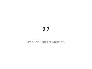
IP Address Format 24 bits 7 bits 0 netid hostid Class A 16 bits 14 bits Class B 10 netid hostid 21 bits 8 bits Class C 110 netid hostid 28 bits Class D 1110 Multicast group ID
IP Address Format (cont.) • Different size networks may use different address classes, defined by the first few bits in the address. 0 for Class A, 10 for Class B, 110 for Class C, etc. etc. • Networks with large numbers of hosts may use Class A, while Class C may have many subnets with a small number of attached hosts.
IP Address Notation • A decimal dot notation is used to break down the IP address. • Example • 10001000 11001110 00001011 00000110 • gives the address 136.206.11.6 aka boole ! • Note that this is a Class B address (first zero in second position) and the subnet is defined with 14 bits, the host address with 16 bits.
IP Allocations • A central authority has responsibility for allocation of IP addresses. They are the network Information center, or NIC.
Specail IP Addresses • Class D addresses are for multicasting. • Class E are experimental • Private blocks include • 10.0.0.0 – 10.255.255.255 (10.0.0.0/8) • 172.16.0.0 – 172.31.255.255 (172.16.0.0/12) • 192.168.0.0 – 192.168.255.255 (192.168.0.0/16) • 127.0.0.1 Loopback address
Subnetting • Subnetting allows for the creation of multiple logical networks within a single Class A, B or C network • Instead of using 16 bits for the hosts, divide the host space up into 2, a subnet and a host • If you have a Class B network, you can connect up to 64 thousand hosts. Think of DCU. Need to break up network into EE, CA, Communications, etc., so we subnet the network • Subnet masks • Class A = 255.0.0.0 • Class B = 255.255.0.0 • Class C = 255.255.255.0
Subnet Network Subnet Host Subnetting a Class B network 10 Network 512 networks, 126 hosts /25 10 Network Subnet Network Subnet Host 254 networks, 254 hosts /24 10 Network Subnet Network Subnet Host 128 networks, 510 hosts /23 10 Network Subnet Network Subnet Host 64 networks, 1,022 hosts /22 10 Network Subnet Network Subnet Host 32 networks, 2,046 hosts /21
Subnetting • Normally when a router receives a packet it looks at the IP address and decides if it is local or has to sent elsewhere. Entries look like (network, 0) and (this-network, host). The routing table has entries for local packets as well as distant packets. A router only needs to know about its local hosts, some other networks and where to send all other packets • With subnetting an extra entry is added to the routing table stating (this-network, subnet, 0) and (this-network, this-subnet, host) • This way a router knows about all of its own hosts and how to get to the other subnets
Subnet Mask • Router has a subnet mask telling it the split between (subnet) networks and hosts • Subnetting is not visible outside the network • Boolean AND to remove host part • 136.206.19.34 • 255.255.255.0 • 136.206.19.0
Subnetting • To recap, subnetting divides an organisations single class A, B or C network into multiple logical networks by dividing the original host identifier string into two, with the first string representing the subnet and the second representing the hosts • Routers use a subnet mask to determine if a packet is to be routed to the current network, another network in the subnet or a distant network
TCP/IP Encapsulation user Data Appl Hdr user Data Application TCP header Application Data TCP IP header TCP header Application Data IP Ethernet header IP header TCP header Application Data Ethernet trailer 802.3
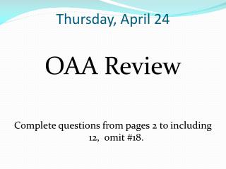
TCP Segment Header 16-bit source port number 16-bit destination port number 32-bit sequence number 32-bit acknowledgement number 4bit hdr length reserved u r g A C K P S H R S T S Y N F I N 16-bit window size 16-bit TCP checksum 16-bit urgent pointer Options (if any) Data (if any)
TCP Header Description • Source Port and Destination Port identify transport end-points of connection. • Sequence Number and Acknowledgement Number perform usual functions, Ack numbers next byte expected. • TCP Header Length indicates number of 32 bit words in header. Length varies because of options. • Not used. No bug fixes required !
Six one bit flags… • URGent pointer in use, used for indicating interrupts and offset from seq no. to urgent data. • ACK bit used to indicate piggybacked acknowledgement. • PSH requests that receiver does not buffer but to deliver. • RST is reset connection, means problems ! • SYN used in conjunction with ACK to request connection. • FIN release connection
Window size used for variable-sized sliding window. Size of zero indicates a choke packet. • Checksum checks header. • Options field for things like specification of maximum TCP payload. Negotiated at startup lowest bid wins. • A selective repeat instead of go-back-n sliding window protocol may be specified as an option.
TCP Addressing • TCP uses notion of Port Number to access transport endpoint on a single host. Many Ports may be in use simultaneously. • Combination of IP address and port number uniquely identifies a port for process running on a particular machine. • Process may even have several ports open.
TCP Services • Provides connection-oriented, reliable, byte stream service. • Segments passed to IP for routing, timer attached for each segment. • Sliding window protocol utilised with go-back-n or selective-repeat for retransmission. • All TCP segments acknowledged.
TCP segments may arrive out of order, sliding window will sort order. • TCP segments may be duplicated, duplicated are discarded. • TCP provides flow control, no process\host will be swamped, helps avoid congestion. • TCP utilised by many internet applications such as Telnet, Rlogin, FTP, E-mail, WWW Browsers.
TCP – The Guts What programmers need to know
Three Way Handshake Socket, Bind, Listen Accept(blocks) Socket Connect(blocks) (active open) SYN J SYN K, ack J+1 Connect returns Ack K+1 Accept returns Read(blocks
Server prepares connection • socket, bind, listen. This is a passive open. • Client issues active open by calling connect. • Issues a SYN segment with sequence no. • Contains IP header, TCP header and possible TCP options (next slide) • Server acks clients SYN with its own SYN with initial sequence no that server will send. The SYN and ACK are sent is the same segment. • Client acknowledges the servers SYN • 3 packets are sent (minimum) so called 3-way-handshake.
Common TCP Options in SYN • MSS: maximum segment size (Stevens Ch 7.9) • Window Scale Option: max window 65535 (16 bit size). Window may be scaled (left shifted) by 0-14 bits giving amx window size of 65535 x 214. Only used if both sender and receiver agree. • Timestamp option: used on hi-speed connections to prevent corruption due to reappearing packets, negociated similarely to above. • Latter two called RFC 1332 options, or “long fat pipe options”
TCP Connection Termination • If application calls close forst, this is an active close. • Sends FIN segment, meaning finished sending data. • Server performs passive close. • Clients FIN is ack’ed and sent to application as EOF, after any queued data to receive. • When application receives its EOF, it will close its socket. TCP sends FIN. • The server on receiving final FIN acks that FIN.
Close (active close) FIN M (passive close) read returns 0 close ack M+! FIN N ack N+1
TCP SDT • Normal client transitions • Normal Server transitions • appl: Application issues operation • recv: segment received • send: what is sent for this transition • The netstat applicationuses the state names from this diagram, try it out.
starting point closed appl:passive open send<nothing> Appl: active open Send SYN listen recv: SYN; send: SYN, ACK active open recv: RST recv: SYN send: SYN, ACK simultaneous open SYN_RCVD SYN_SENT recv:ACK send<nothing> recv:SYN, ACK send: ACK ESTABLISHED data Transfer state CLOSE_WAIT recv: FIN send: ACK appl: close send: FIN appl: close send: FIN recv: ACK send: <nothing> LAST_ACK
appl: close send: FIN simultaneous close recv:FIN send: ACK CLOSING FIN_WAIT_1 recv: FIN, ACK send: ACK recv: ACK send: <nothing> recv: ACK send: <nothing> recv: FIN send: ACK TIME_WAIT FIN_WAIT_2 2MSL timeout
11 states defined. Rules of TCP apply… • If application performs active open in CLOSED state, TCP sends SYN and new state is SYN_SENT. • If TCP next receives a SYN with an ACK, it sends an ACK and the new stste is ESTABLISHED • Two arrows leading from ESTABLISHED deal with termination. • If application calls close before receiving eof (active close), transits to FIN_WAIT_1 • If application receives FIN while ESTABLISHED (passive close), transits to CLOSE_WAIT
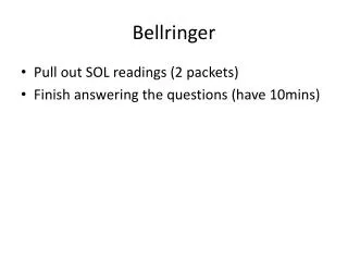
TCP Connection & The Packets • A complele TCP connection involves many packet exchanges. • Connection establishment • Data transfer • Connection termination • TCP states are also shown as client and server enter them.
Client Server socket, bind, listen LISTEN(passive open) accept(blocks) SYN_RCVD ESTABLISHED accept returns read(blocks) read returns <server process request> write read(blocks) CLOSE_WAIT(passive close) read returns 0 close LAST_ACK CLOSED SYN J, mss=1460 Socket Connect(blocks) (active open) SYN_SENT ESTABLISHED Connection returns <client forms request> Write Read(blocks) Read returns Close (active close) FIN_WAIT_1 FIN_WAIT_2 TIME_WAIT SYN K, ack J+1, mss=1024 ack K+1 Data (request) Data reply Ack of request ack of reply FIN M ack M+! FIN N ack N+1
Client announces MSS 1460, typical for Ethernet, Ok if different in each direction. • Once connection established, clients forms request for server. • Server processes request and replies with piggybacked ack. • Termination by client (active close) enters TIME_WAIT state, 2MSL (Maximum Segment Lifetime) to deal with lost or wandering IP packets.