Download
1 / 46
480 likes | 716 Views
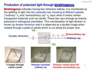
Use of polarized light imaging and sensing in the clinical setting . Jessica C. Ramella-Roman, PhD. Short Bio. Laura in Electrical Engineering, University of Pavia, Italy (93) MS and PhD in Electrical Engineering from Oregon Health & Science University (04) Advisor Steve Jacques

E N D
Use of polarized light imaging and sensing in the clinical setting Jessica C. Ramella-Roman, PhD
Short Bio • Laura in Electrical Engineering, University of Pavia, Italy (93) • MS and PhD in Electrical Engineering from Oregon Health & Science University (04) • Advisor Steve Jacques • Thesis on use of polarized light in biophotonics • Post doc at Johns Hopkins, APL (04,05) • Polarized light interaction with rough surfaces
Short Bio cnt. • Associate Professor in Biomedical Engineering (05-present) at CUA • Adjunct A. Prof. Johns Hopkins School of Medicine (06-present) • Guest Researcher NIST (04- present) • Research – faculty.cua.edu/ramella • Tissue oximetry, retina, skin using reflectance spectroscopy and MI • Small vessel Flowmetry and structural analysis • Polarized light imaging and sensing for the detection of skin cancer, vascular abnormalities
Course outline Lecture 1- Introduction and fundamentals of polarimetry Lecture 2- Experimental Stokes and Mueller matrix polarimetry Lecture 3 – Modeling – Monte Carlo 1 Lecture 4 – Modeling – Monte Carlo 2 Lecture 5 – Clinical applications of polarized light sensing
Polarized light in bio-photonics 64 • Filtering mechanism • Skin cancer imaging • Imaging of superficial features • Vasculature • others *JBO 2002
Filtering mechanism y 64 x ~2-4% parallel, sub surface 100% parallel incidence ~4% parallel surface glare 40% unpolarized Epidermis papillary dermis reticular dermis 53% absorbed
Filtering mechanism-surface glare y 64 64 x ~2-4% parallel, sub surface 100% parallel incidence ~4% parallel surface glare 40% unpolarized Epidermis papillary dermis reticular dermis 53% absorbed
Filtering mechanism-single scattering y 64 64 x Co polarized ~2-4% parallel, sub surface 100% parallel incidence ~4% parallel surface glare 40% unpolarized Epidermis papillary dermis reticular dermis 53% absorbed
Filtering mechanism-multiple scattering y 64 64 x ~2-4% parallel, sub surface 100% parallel incidence ~4% parallel surface glare Cross polarized 40% unpolarized Epidermis papillary dermis reticular dermis 53% absorbed
Polarized light imaging of skin cancer 64 H & V H
par per - = Polarized image par per + Par = Superficial + Deep Per = Deep Enhance superficial structures such as skin cancer margins
Polarized imaging:Basal-Cell Carcinoma 64 Unpolarized Polarized
compound nevus normal pol 1-cm ruler
freckle normal pol
θs θi α α Air γ Skin top surface Fresnel Reflection Imaging of superficial features • Polarization signature of roughness • Cosmetic industry and rendering community • Skin cancer
Vasculature enhancement ~2-4% parallel sub surface 100% parallel incidence ~4% parallel surface glare 40% unpolarized capillary 53% absorbed transillumination
Other techniques that use polarization • Mueller matrix imaging - colon cancer • De Martino et al. Opt. Exp. 2011 • Polarized light scattering spectroscopy – eliminate multiple scattering with co/cross polarized layout • V. Backman et al. Nature 2001 • PS OCT – birefringence / structural components • De Boer, Opt. Exp. 2005 • Particle sizing • (….)
Polarization basics *Ghosh et al. JBO 2011 Polarization is a property that arises out of the transverse (and vector) nature of the electromagnetic (EM) radiation It describes the shape and the orientation of the locus of the electric field vector (Ε) extremity as a function of time, at a given point of the space*.
Electric Field vector (EM) Y dx, dy =phases w =light frequency k= 2p/l Eox,Eoy, =magnitude of electric field l =wavelength of light in free space E Eoy Eox X Z
y 2E0y h x 2E0y Polarization Ellipse
Jones vector formalism Advantages: - Measurement of coherence and time dependent phenomena - Speckle based techniques Disadvantage -Cannot handle depolarization dx, dy= phases Eox,Eoy, = magnitude of electric field
Jones matrix Polarized transfer of light – interaction with a medium J is a 2x2 complex matrix
Stokes vector formalism Intensity based representation Characterize the polarization state of light E0x, E0y, Cartesian electric field component d=dx-dy phase difference
Stokes vector formalism Advantages: - Handles depolarization - Easy experimental application Disadvantage - Cannot handle coherence Four measurable quantities (intensities) Characterize the polarization state of light G.G. Stokes (1852)
Stokes vector formalism Four measurable quantities (intensities) Characterize the polarization state of light G.G. Stokes (1852) Restriction on the Stokes parameters
Poincaré sphere • A geometrical representation of Stokes vectors • Sphere with unit radius • Linearly polarized states are on the equator • Circularly polarized states are at the poles • Partially polarized states are inside the sphere
Linearly polarized light = E0x = E0y
Linearly polarized light = E0x = E0y
Linearly polarized light = -E0x
Unpolarized light • Unpolarized light cannot be described through a Jones vector • Stokes vector and Mueller matrix formalism is mostly used in biophotonics
Mueller matrix i, input o, output
Mueller matrix cnt. i, input o, output Multiple Mueller Matrices Mi
Scattering matrix • Mie theory • Spheres, spheroids, cylinders D=0.01µm If not Stokes vector must be rotated onto that plane Scattering must be in reference plane
Mueller Matrixfrom microspheres solutions m11 m44 *Cameron et al. JBO 2001 D= 2µm
y 2E0y h x 2E0y Principal angle of polarization Polarization Ellipse
Tomorrow Experimental application of polarimetry Introduction to a typical Stokes vector polarimeter Introduction to a typical Mueller Matrix polarimeter