Download
1 / 29
290 likes | 486 Views
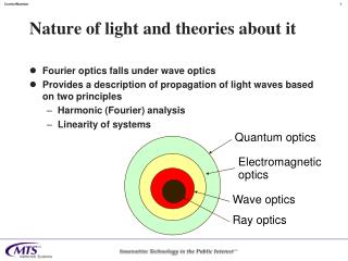
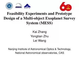
Kai Zhang Yongtian Zhu Lei Wang Nanjing Institute of Astronomical Optics & Technology, National Astronomical observatories, CAS. Feasibility Experiments and Prototype Design of a Multi-object Exoplanet Survey System (MESS). Content. Introduction of a Multi-object Exoplanet Survey System

E N D
Kai Zhang Yongtian Zhu Lei Wang Nanjing Institute of Astronomical Optics & Technology, National Astronomical observatories, CAS Feasibility Experiments and Prototype Design of a Multi-object Exoplanet Survey System (MESS)
Content Introduction of a Multi-object Exoplanet Survey System • Principle of operation • Feasibility experiments Prototype design • Optical and Mechanical design • Temperature Sensitivity • Anti-vibration & Optical processing problem
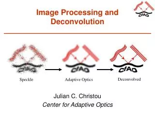
Principle of Operation • Theoretical basis: External Dispersed Interferometer (EDI) ——David Erskine et, al. in 1997 • System Composition: Telescope(2~4m); Fixed Delay Michelson Interferometer; Medium Resolution Spectrometer (R5,000~20,000) Advantage: Interferometer fringes and spectrum yield Moiré effect to enhance the measuring precision of radial velocity shift.
Spectrometer Without EDI, spectrum line shift is measured With EDI, spectrum phase shift is measured EDI devices Telescope Principle of Operation Figure of Principle: Phase shift of Moiré fringes is obviously more 5~6 times sensitive than spectrum line shift without EDI.
Principle of Operation System: A Multi-object Exoplanet Survey System based on LAMOST is being developed. • 4m LAMOST telescope and its fibers • Multi-object Fixed Delay Michelson Interferometer • LAMOST Low Resolution Spectrometer (LRS) (works in Medium Resolution mode) Observatory objects: • 60% dwarf, mainly sun-like type; 30% G, K type Giant and sub-Giant; 10% M type dwarf. • 8~12V
Principle of Operation Fig. Scheme of system based on LAMOST
Feasibility Experiment In Oct. 2008~Feb. 2009, some feasibility experiments were processed in lab. Result: • Basically prove the principle of EDI • Gain some data of interferometer spectrum • Aware of some problem about developing the devices … …
Optical Fiber Light Spectrometer Interferometer Fig. Experiment in Jan. 2009 Feasibility Experiment Figures of feasibility experiment: Fig. Experiment in Oct. 2008
Feasibility Experiment Figures of feasibility experiment: (λ 0.51~0.55um) Fig. Interferometer spectrum of Hg, in Oct. 2008 Fig. Interferometer spectrum of Mo, in Jan. 2009 Fig. Binary objects’ Interferometer spectrum of Mo, in Jan. 2009 Fig. Phase shift without any anti-vibration, in Jan. 2009
Prototype Design According to the feasibility experiment and results, prototype design is given. Design: Multi-object Fixed Delay Michelson Interferometer (FDMI) is the key device of MESS. • Optical and mechanical design • Modularization (3 units per a module) • Simplify and minimize the structure • High installation accuracy • Temperature Sensitivity • Anti-vibration & Optical processing problem (Ongoing)
Fiber Slit Fiber Fiber Fig. optical design of a module Optical and Mechanical Design Figure of prototype design :
Optical and Mechanical Design Figures of prototype design : Fig. Mechanical design of a module
Optical and Mechanical Design Some difficulties: • Multi-object (~40 object) • Limitation of slit (0.16~0.32mm; limited space) • Low optical efficiency (fiber coupling; transmission; vignette effect) • Performance index (fixed delay 1~2mm; 4~6 fringes) • High installation and stability accuracy … …
Temperature Sensitivity Analysis: Analysis of temperature sensitivity has been done, especially about the fixed delay. Delay of interferometer changes with wavelength, temperature and incident angle. So the analysis was done in the following way: • Plane effect (influencing factors) • Glass cube (Data and evaluation) • Defocusing effect (Optimization) • Radial velocity shift with temperature
Plane Effect Three influencing factors: The delay of Michelson interferometer, also called OPD, is required to be a fixed one, like a plane. But temperature and incident angle, which are respectively along two different orientations, like two forces to twist the plane. Third force, wavelength, also contributes the change of delay, like an elevator to lift the plane up or down. For compensating these forces, the interferometer design borrows ideal from WAMI*, and set up seven conditions. … … *WAMI, firstly introduced by R. L. Hilliard and G. G. Shepherd, in 1965
Glass Cube Two compensation processes: A process of choosing different length and materials of armsto give the required delay is known as field compensation since it allows a much larger acceptance angle for the interferometer. Another process of choosing the better glass pair from all of samples, is suggested as evaluation function to degrade its temperature and wavelength sensitivity. So, three coefficients of every glass type is given. The gain coefficient of refractive index with wavelength Thermal line expansion coefficient The gain coefficient of refractive index with temperature
Glass Cube Glass cube: Actually, seven above conditions can’t be perfectly and stimulatingly satisfied by real glass types. So a kind of glass data, we call ‘glass cube’, is given to evaluate every sample of glass pair. Every glass cube is an array data offour dimensions that respectively represents delay, wavelength, temperature and incident angle. And their data are gain from some function of three above coefficients. … …
Defocusing effect Optimization: After two above processes, the number of samples decrease from 2883 to 40. For further widening angle at a wide waveband, a defocusing effect is suggested as optimization method. The result is shown that makes acceptance angle larger by 10~20%. Finally, a manual selection is done for choosing the best one of all the above samples. In the following figures, the results of defocusing effect are respectively shown. ——Ref. SCHOTT Glass Data, 2009.
Defocusing effect Analog figures:(N-LAK34 / BAF10) Fig. without defocusing effect Fig. with defocusing effect If the max required delay error is 0.05 waves @527.4nm (blue dot line) With defocusing effect, the acceptance angle widens by ~13%.
Defocusing effect Analog figures:(N-LASF31 / N-LASF45) Fig. without defocusing effect Fig. with defocusing effect If the max required delay error is 0.05 waves @527.4nm (blue dot line) With defocusing effect, the acceptance angle widens by ~19%.
Radial Velocity with Temperature Radial velocity shift with temperature: with analysis of delay, radial velocity shift with temperature is given by the Doppler function. If keeping the shift under 1m/s, the temperature would be stable in a small range. So a smaller radial velocity shift with temperature required becomes an important condition for selecting the suitable sample.
Radial Velocity with Temperature Figures of delay shift with temperature: Fig. delay shift with temperature of Fig. delay shift with temperature of N-LAK34 / BAF10 N-LASF31 / N-LASF45
Radial Velocity with Temperature Figures of Radial velocity shift per degree: Fig. Radial velocity shift of Fig. Radial velocity shift of N-LAK34 / BAF10 N-LASF31 / N-LASF45 According to two above figures, the environment’s temperature respectively needs to keeping in a range of 2mK for radial velocity shift of 1m/s.
Ongoing Other problems: • Anti-vibration Phase stability is required to 1/8 waves per 30 min. • Optical processing Internal reflection mirror with optical wedge. • Optical contact Epoxies used to join up the components might exhibit some level of creep as the epoxy shrinks. • Beam splitter coating A particular non-polarizing coating is designed to yield a close 50-50 split in a large range of incident angle.
Ongoing Figures of beam splitter: Optical path through a beam splitter is a dual path. So the ideal transmission is 25% per split ray. Fig. beam splitter with designed incident angle of 45°and field of view of 20° Fig. beam splitter with designed incident angle of 30°and field of view of 20°
Ongoing Analog figures of beam splitter coating: Fig. Beam splitter coating 30° Fig. Beam splitter coating 45° Two above figures are respectively two kinds of dual transmission of non-polarizing 50-50 coating with incident angle of 30°and 45°.
Ongoing Analog figures of beam splitter coating: Fig. Beam splitter coating 30°(-10°) Fig. Beam splitter coating 30°(+10°) Two above figures are respectively the dual transmission of non-polarizing 50-50 coating with boundary angle of 20°and 40°.
Ongoing Analog figures of beam splitter coating: Fig. Beam splitter coating 45°(-10°) Fig. Beam splitter coating 45°(+10°) Two above figures are respectively the dual transmission of non-polarizing 50-50 coating with boundary angle of 35°and 55°.
Thanks for your attention 张 凯 Japan. Oct. 2009