Understanding I/O: Connecting to the Outside World in Computing Systems
290 likes | 423 Views
In this chapter, we delve into input/output (I/O) operations, exploring how data moves between registers and memory, and how external devices communicate with the CPU. We will discuss control/status registers, data registers, and the critical role of polling versus interrupts in data transfer management. The chapter explains memory-mapped I/O versus special instructions, and the concept of asynchronous vs. synchronous operation. By the end, readers will understand how devices like keyboards and displays interact with the CPU, enhancing human-computer interaction.

Understanding I/O: Connecting to the Outside World in Computing Systems
E N D
Presentation Transcript
I/O: Connecting to Outside World • So far, we’ve learned how to: • compute with values in registers • load data from memory to registers • store data from registers to memory • But where does data in memory come from? • And how does data get out of the system so thathumans can use it?
I/O Controller • Control/Status Registers • CPU tells device what to do -- write to control register • CPU checks whether task is done -- read status register • Data Registers • CPU transfers data to/from device • Device electronics • performs actual operation • pixels to screen, bits to/from disk, characters from keyboard Graphics Controller Control/Status CPU Electronics display Output Data
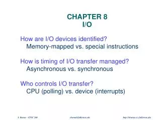
Programming Interface • How are device registers identified? • Memory-mapped vs. special instructions • How is timing of transfer managed? • Asynchronous vs. synchronous • Who controls transfer? • CPU (polling) vs. device (interrupts)
Memory-Mapped vs. I/O Instructions • Instructions • designate opcode(s) for I/O • register and operation encoded in instruction • Memory-mapped • assign a memory address to each device register • use data movement instructions (LD/ST)for control and data transfer
LC-3 • Memory-mapped I/O(Table A.3) • Asynchronous devices • synchronized through status registers • Polling and Interrupts • the details of interrupts will be discussed in Chapter 10
Simple Implementation: Memory-Mapped Input Address Control Logic determines whether MDR is loaded from Memory or from KBSR/KBDR.
Input from Keyboard • When a character is typed: • its ASCII code is placed in bits [7:0] of KBDR(bits [15:8] are always zero) • the “ready bit” (KBSR[15]) is set to one • keyboard is disabled -- any typed characters will be ignored • When KBDR is read: • KBSR[15] is set to zero • keyboard is enabled keyboard data 15 8 7 0 KBDR 15 14 0 ready bit KBSR
Basic Input Routine POLL LDI R0, KBSRPtr BRzp POLL LDI R0, KBDRPtr ... KBSRPtr .FILL xFE00KBDRPtr .FILL xFE04 new char? NO Polling YES readcharacter
Output to Monitor • When Monitor is ready to display another character: • the “ready bit” (DSR[15]) is set to one • When data is written to Display Data Register: • DSR[15] is set to zero • character in DDR[7:0] is displayed • any other character data written to DDR is ignored(while DSR[15] is zero) output data 15 8 7 0 DDR 15 14 0 ready bit DSR
Basic Output Routine POLL LDI R1, DSRPtr BRzp POLL STI R0, DDRPtr ... DSRPtr .FILL xFE04DDRPtr .FILL xFE06 screen ready? NO Polling YES writecharacter
Simple Implementation: Memory-Mapped Output Sets LD.DDR or selects DSR as input.
Keyboard Echo Routine • Usually, input character is also printed to screen. • User gets feedback on character typedand knows its ok to type the next character. new char? POLL1 LDI R0, KBSRPtr BRzp POLL1 LDI R0, KBDRPtrPOLL2 LDI R1, DSRPtr BRzp POLL2 STI R0, DDRPtr ... KBSRPtr .FILL xFE00KBDRPtr .FILL xFE02DSRPtr .FILL xFE04DDRPtr .FILL xFE06 NO YES readcharacter screen ready? NO YES writecharacter
Transfer Control • Who determines when the next data transfer occurs? • Polling • CPU keeps checking status register until new data arrives OR device ready for next data • “Are we there yet? Are we there yet? Are we there yet?” • Interrupts • Device sends a special signal to CPU whennew data arrives OR device ready for next data • CPU can be performing other tasks instead of polling device. • “Wake me when we get there.”
Interrupt-Driven I/O • External device can: • Force currently executing program to stop; • Have the processor satisfy the device’s needs; and • Resume the stopped program as if nothing happened. • Why? • Polling consumes a lot of cycles,especially for rare events – these cycles can be usedfor more computation. • Example: Process previous input while collectingcurrent input. (See Example 8.1 in text - page 221.)
Interrupt-Driven I/O • To implement an interrupt mechanism, we need: • A way for the I/O device to signal the CPU that aninteresting event has occurred. • A way for the CPU to test whether the interrupt signal is setand whether its priority is higher than the current program. • Generating Signal • Software sets "interrupt enable" bit in device register. • When ready bit is set and IE bit is set, interrupt is signaled. interrupt enable bit 0 15 14 13 ready bit KBSR interrupt signal to processor
Priority • Every instruction executes at a stated level of urgency. • LC-3: 8 priority levels (PL0-PL7) • Example: • Payroll program runs at PL0. • Nuclear power correction program runs at PL6. • It’s OK for PL6 device to interrupt PL0 program,but not the other way around. • Priority encoder selects highest-priority device,compares to current processor priority level,and generates interrupt signal if appropriate.
Testing for Interrupt Signal • CPU looks at signal between EXECUTE and FETCH phases. • If not set, continues with next instruction. • If set, transfers control to interrupt service routine. Fetch NO interrupt signal? YES Transfer to ISR Decode Execute More details in Chapter 10.