
Low-Cost Educational Controller for Electric Drives
An educational prototype controller for induction motor control, emphasizing key concepts for student understanding. Features voltage/frequency control and practical laboratory experiments.

Low-Cost Educational Controller for Electric Drives
E N D
Presentation Transcript
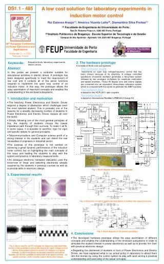
2. The hardware prototype It consists of three main sub-systems: Keywords: Education tools, laboratory experiments, electric drives. Abstract In this poster we present a controller suitable for educational activities in electric drives. A prototype has been designed specifically to meet the requirement of low cost and it contains all of the active functions required to implement the open loop control of an induction motor. In this way, the prototype allows the easy assimilation of important concepts and enables the understanding of the enclosed subsystems. The controller board implements an open loop voltage/frequency control that has been chosen because of its simplicity. A voltage controlled quadrature sinusoidal oscillator generates a two-phase system followed by two analogue multipliers for amplitude modulation and speed inversion. These 90 degree sine and cosine signals are converted into an equivalent three-phase reference system which is compared with the carrier to generate the IGBT’s pulses. The isolation boar is based on the HCPL2611 opto-couplers The power board is based on International Rectifier’s IRMDAC3 Design Kit • 1. Introduction and motivation • The teachingPower Electronics and Electric Drives requires a degree of abstraction which challenges even the most talented student.This is probably one of the reasons for a steadily decreasing number of students in Power Electronics and Electric Drives classes all over the world. • Simply following one of the most general principles of live, the majority of students choose the lowest impedance path through their curricula. To make it all fit, in some cases, it is possible to sacrifice: rigor for vigor and specific details for general principles. • Telecommunications and Computer science profit of a strong interest in the students and can distort the real necessities of engineers in industrial sector. • The purpose of this prototype is not centred on achieving a great dynamic performance of the induction motor control, but on highlighting the main concepts of this issue and leading the students to play with the system and practice in laboratory measurements. • An analogue electronic hardware realization uses the know-how of linear and switching electronics already acquired by the students in previous coursesas well as to provide skills in electronic design. Fig. 1. Block diagram of the present prototype. 3. Experimental results Fig. 3. Electronic circuit for amplitude modulation including rotor speed inversion. Fig. 4. Block diagram of the present prototype. • 4.Conclusions • The developed hardware prototype allows the easy assimilation of different concepts and enables the understanding of the enclosed subsystems in order to stimulate the student interest in power electronics as well as to provide him (her) with practical electronic design. • Regarding the disinterest of students in front of Power Electronics and Electric Drives, we have explained what is our actual policy in laboratory to attract them into this domain by using the control system to play with work aiming a practical understanding and exercising of the actual concepts. Fig. 2. Some results: (a) DC voltages for frequency and amplitude control of the quadrature sinusoids versus DC input voltage control ; (b) the three-phase reference system of voltages in a speed reversal; (c) the three phase sinusoidal reference and carrier signals; (d) the two quadrature sinusoids in an speed reversal ; (e) speed reversal ; (f) the inverter output line-to-line voltage.


