Download
1 / 21
210 likes | 311 Views
Research focuses on understanding damage mechanisms, performance of metal mirrors for laser fusion under typical conditions, including reflectivity and wavefront changes. Budget: $330k. Experiments include mirror fabrication, beam characterization, and reflectometry. Modeling involves scattering results and ZEMAX. Future plans cover new surface types and materials development. Reflectometer monitors surface changes. Damage studies on metal mirrors reveal insights on beam characteristics. Ray tracing and Gaussian surface height statistics are applied.

E N D
Progress on Laser Induced Damage Studiesof Grazing Incidence Metal Mirrors Mark S. Tillack T. K. Mau Mofreh Zaghloul Laser-IFE Program Workshop May 31-June 1, 2001 Naval Research Laboratory
Statement of Purpose and Deliverables Statement of purpose Our research seeks to develop improved understanding of damage mechanisms and to demonstrate acceptable performance of grazing incidence metal mirrors, with an emphasis on the most critical concerns for laser fusion. Through both experimen-tation and modeling we will demonstrate the limitations on the operation of reflective optics for IFE chambers under prototypical environmental conditions. Deliverables (2 mo. delayed funding): Measure LIDT at grazing incidence with smooth surfaces. Sept. 1, 2001 Model reflectivity and wavefront changes of smooth surfaces. Sept. 1, 2001 Measure effects of defects and surface contaminants on reflectivity, LIDT and wavefront. April 1, 2002 Model reflectivity and wavefront changes due to defects and April 1, 2002 contamination. Budget: $330k
Outline 1. Experiments a. Mirror fabrication and characterization b. Beam characterization c. Reflectometry – reflectivity at shallow angles – in-situ damage monitoring d. Damage results at grazing angles – Al 6061 – Al 11002. Modeling a. Scattering results b. ZEMAX3. Future plans
Several new surface types have been fabricated: 1. Diamond-turned flats Al 1100 99.999% pure Al diamond-turned Al 6061 MgSi occlusions
Several new surface types have been fabricated: 2. Sputter coated substrates 75 nm Al on superpolished flat: ±2Å roughness, 10Å flatness Making larger substrates: • Ordinary Si wafers aren’t flat enough (15 microns) • Large polished substrates are expensive • However, substrates can be recycled
Beam characterization has been installed Shack-Hartmann Profiling
Spatial profile and wavefront of the Nd:YAG laser Q ~ 200 mrad
The reflectometer is fully functional and used for in-situ surface monitoring 100 ppm accuracy
In-situ reflectometry can measure surface changes not visible to the naked eye
Shallow angle reflectivity measurements of undamaged surfaces
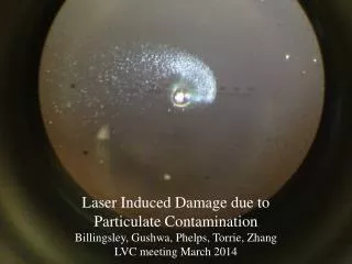
Damage to Al 6061 at grazing angle Several shots at 80˚, 1 J/cm2 peak MgSi Fe Fe 1000x • Damage occurs at a higher fluence compared with normal incidence• Silicide occlusions in Al 6061 preferentially absorb light, causing explosive ejection and melting• Fe impurities appear unaffected
Al 1100 shows no apparent damage at 1 J/cm2 Al 6061, for comparison 1000 shots at 85˚, 1 J/cm2 peak 1000x 200x
Tools for modeling effects of damage on beam characteristics
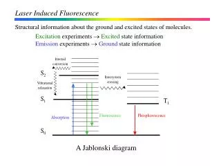
Specularly reflected intensity is degradedby induced mirror surface roughness Isc q2 q1 The effect of induced surface roughness on beam quality was investigated by Kirchhoff wave scattering theory. For cumulative laser-induced and thermomechanical damages, we assume Gaussian surface height statistics with rms height s. 1.0 0.8 0.6 0.4 0.2 0 Iinc q1 = 80o Intensity Degradation, e–g 70o 60o Io : reflected intensity from smooth surface Id : scattered incoherent intensity g : (4ps cosq1/l)2 e.g., at q1 = 80o, s/l = 0.1, e-g = 0.97 0 0.1 0.2 0.3 0.4 0.5 s / l • Grazing incidence is less affected by surface roughness • To avoid loss of laser beam intensity, s / l < 0.01
Ray Tracing with ZEMAX ZEMAX commercial software was installed Example problem: Rays at object plane emitted at three angles. Illumination profile at image plane Tasks: - Evaluate surface deformation from expected loads. - Quantify allowable surface deformation (shape and size) to meet beam propagation requirements (spot size/location, intensity uniformity, absorption).
Goals for next period of performance • Compare damage on 99.999% Al with Al-1100 • Perform tests at 5 J/cm2 • Perform sub-threshold irradiation of amorphous Al to explore recrystallization • Establish methods for creating contaminated surfaces • Obtain samples for neutron irradiation • multi-layer dielectric mirror • Al mirror • Exercise ZEMAX to assess wavefront degradation
Final Optics Program Plan FY 2001 | FY 2002 | FY 2003 | FY 2004 | FY2005 RADIATION DAMAGE (neutron and gamma effects) Scoping Tests: Irradiation & PIE (incl. annealing) Extended testing of prime candidates Damage modeling LASER-INDUCED DAMAGE LIDT scoping tests for GIMM, materials development System Integration Laser damage modeling, 3w data from NIF CONTAMINATION THREATS Modeling Test simulated contaminants Mitigation System Integration X-RAY ABLATION Scoping tests (laser-based x-ray source) Mitigation System Integration Modeling ION SPUTTERING Calculate sputtering, gas attenuation Mitigation System Integration