Download
1 / 21
210 likes | 363 Views
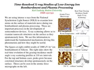
UV laser-induced damage to grazing-incidence metal mirrors. M. S. Tillack, J. Pulsifer, K. Sequoia. 4th US-Japan Workshop on Laser-Driven Inertial Fusion Energy Technology Osaka University March 13-15, 2003. Design concept for a grazing-incidence metal mirror.

E N D
UV laser-induced damage to grazing-incidence metal mirrors M. S. Tillack, J. Pulsifer, K. Sequoia 4th US-Japan Workshop on Laser-Driven Inertial Fusion Energy Technology Osaka University March 13-15, 2003
Design concept for a grazing-incidence metal mirror Issues:• Shallow angle instability• Damage resistance/lifetimeGoal = 5 J/cm2• Optical quality• Fabrication The mirror consists of a stiff, radiation-resistant substrate with a thin metallic coating optimized for high reflectivity
Metal reflectors are chosen due to concerns over radiation damage to multi-layer dielectrics Normal incidence reflectivity of various metals vs. wavelength Reflectivity of oxidized Al to s-polarized light 248 nm High reflectivity at shallow angles gives aluminum a potentially high damage threshold
Outline of the talk: • UV damage testing of mirrors in air; comparisons with visible light • Damage testing in vacuum • Preliminary data on contaminated surfaces • Coated vs. solid optics • Perturbations to transmitted light
Optics were tested using a 0.4-J KrF laser 420 mJ, 25 ns, 248 nm
Single-shot damage of pure Al in air 100mm earlier data @532 nm 1 shot, 40 J/cm2 UV light is more damaging than visible light: – Higher photon energy – Interaction with smaller surface features Single-shot damage appears well below the melting point
Cyclic damage in air appears to be correlated with grain boundaries 10mm 104 shots, 40 J/cm2 @532 nm 6744 shots, 10-24 J/cm2 Slip lines are not observed at 248 nm as with visible light
Specularly reflected intensity is degradedby induced surface roughness • The effect of induced surface roughness on beam quality was investigated using Kirchhoff wave scattering theory. Isc 1.0 0.8 0.6 0.4 0.2 0 Iinc q2 q1 q1 = 80o Intensity Degradation, e–g 70o 60o Io : reflected intensity from smooth surface Id : scattered incoherent intensity g : (4ps cosq1/l)2 e.g., at q1 = 80o, s/l = 0.1, e-g = 0.97 0 0.1 0.2 0.3 0.4 0.5 s / l • Grazing incidence is less affected by Gaussian surface roughness • To avoid loss of laser beam intensity, s / l < 0.1 ~ 25 nm
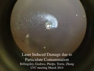
The appearance of chemical reactions led us to begin testing in vacuum • A small, fixed-geometry vacuum cell was built to perform scoping tests • Base pressure ~20 mm • Damage is monitored visually; In-situ profile monitoring is being evaluated
The morphology of damage in vacuum is clearly different than in air 500x 1000x 10mm • Small surface features lead to characteristic blue flourescence after 450 shots at 10-20 J/cm2 • Fluence level where defects appear is not much higher than in air, although catastrophic destruction was not observed • Damage is not visible to the naked eye in post-test inspection
Diamond-turning lines are etched 450 shots at 10-20 J/cm2
Possible contamination source: hydrocarbon from target or from chamber walls An oil-contaminated surface was cleaned in 5-10 shots w/o evidence of damage • Initial shots caused explosive combustion of oil • After 5-10 shots at 6-15 J/cm2 the oil was completely cleaned from the beam footprint • Subsequent testing to 100 shots showed no evidence of damage
Possible contamination source: aerosol and particulate from evaporated chamber mat’ls A mineral-contaminated surface exhibited similar behavior Laser footprint • Initial shots exhibited benign (yellow) emission of light • After ~5 shots at 6-15 J/cm2 the contaminant was cleaned from the beam footprint • Subsequent testing to 100 shots showed no evidence of damage
Coated optics are currently being evaluated • Substrate types • superpolished CVD-SiC • functionally graded SiC foam • SiC/SiC composite • Coatings: • RT evaporation coating (120 nm) • PVD coating by magnetron sputtering at 150˚C (300–1400 nm) • others under investigation
Interface thermal stress can be very high • Plane stress analysis • Stress at free surface ~ 0 • Peak stress at inteface • 40 MPa @30 ns • Yield stress ~10 MPa
Coating quality deteriorates above 300 nm 1 mm coating of Al on SiC 300 nm coating of Al on SiC
MER PVD coating - 1st attempt • Imperfect surface exposed to 5 J/cm2 in air for 1000 shots • No laser damage could be found anywhere on the surface
CVD SiC substrate coated with 300 nm Al • Surface exposed to 4-8 J/cm2 in air for several shots • Immediate damage occurred again due to poor substrate
The transmitted wave is an important diagnostic for surface damage The requirement on “damage” is ~2% change in spatial profile and not the appearance of visible damage
Surface map of mirror scan An old, damaged diamond-turned surface was used to highlight various changes to the transmitted beam Surface map Measurements were made using an 8-bit camera with 640x480 resolution We plan to acquire a 12-bit XGA camera for future studies
Summary & Conclusions • No evidence of a “shallow angle instability” has been observed. • Irradiation at 248 nm exhibits much more severe environmental interactions, requiring testing in vacuum. • Cleaning by UV light appears to be a very important effect: • Surfaces must be preconditioned • External contaminants may be tolerable • For coated optics, damage resistance depends on the fabrication technique - coating studies are now underway. • Future damage studies will concentrate on the reflected wavefront rather than visible damage.