Download
1 / 20
200 likes | 265 Views
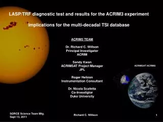
LASP/TRF diagnostic test and results for the ACRIM3 experiment I mplications for the multi-decadal TSI database. ACRIM3 TEAM Dr. Richard C. Willson Principal Investigator ACRIM Sandy Kwan ACRIMSAT Project Manager JPL Roger Helizon Instrumentation Consultant Dr. Nicola Scafetta

E N D
LASP/TRF diagnostic test and results for the ACRIM3 experiment Implications for the multi-decadal TSI database ACRIM3 TEAM Dr. Richard C. Willson Principal Investigator ACRIM Sandy Kwan ACRIMSAT Project Manager JPL Roger Helizon Instrumentation Consultant Dr. Nicola Scafetta Co-Investigtor Duke University ACRIMSAT/ACRIM3 Richard C. Willson
ACRIM3 Guidance from the NASA 2009 Senior Review Senior Review 2009 directed task areas: ACRIM Gap (TSI trends) Annual signal (short term variability) Scale difference (Calibration) Richard C. Willson
Investigation of ACRIM3 - TIM TSI Scale Difference • Approach: Characterize ACRIM3_EM (flight backup) instrument at the LASP/TRF 1 • The LASP/TRF team led by Greg Kopp conducted the TRF testing including: • Comparison of ACRIM self-calibration with the TRF cryo-radiometric scale • Diagnostic testing to measure ACRIM scattering and diffraction effects • The ACRIM3 Team accomplished the following: • Prepared the ACRIM and operated the Instrument at the TRF • Analyzed ACRIM TRF data and provided results to LASP and NRL2 • Derived scale/scattering/diffraction corrections for ACRIM3 observations • Applied corrections to ACRIM3 database and ACRIM Composite TSI time series • NRL led by Jeff Morrill participated and: • Provided independent oversight as TRF testing observers • Convened a review of the process and findings (Dec. 2010) • Conducted independent scattering, diffraction, cavity reflectance modeling/testing • Is preparing a final report on NRL activities • 1 Laboratory for Astronomy and Space Physics (LASP) Total Solar Irradiance Radiometer Facility (TRF) • 2Naval Research Laboratory (NRL) Richard C. Willson
ACRIM3 Sensor • Most key components fabricated during ACRIM3 flight instrument build • ACRIM3_EM representative of ACRIM3 flight instrument properties and performance Richard C. Willson
Laboratory for Atmospheric And Space Physics (LASP) Total Solar Irradiance Radiometer Facility (TRF) ACRIM3_EM Instrument Moveable Transfer Stage Test Chamber Collimator 532nm transfer laser Steering Mirror TRF Cryogenic Radiometer Richard C. Willson
ACRIM3 Sensor Module and Irradiance Testing Modes 15mm Circular Beam Over-fill View Limiting aperture Calibrates total scattering & diffraction 5mm Circular Beam Under-fill Primary aperture Basic Power measurement in SI Units Front View of Sensor Module 10mm Circular Beam Over-fill primary aperture, Under-fill View Limiting aperture and Baffle Calibrates scattering in lower view limiting assembly Richard C. Willson
ACRIM3 LASP/TRF Characterization Results • October 2010 results • Basic optical power scale: ACRIM3 sensors and TRF agree within +/- ~ 500 ppm • Significant scattered light signal from ACRIM3 view-limiter (~ 5000 - 6000 ppm) • ACRIM3_EM precision apertures not conform to ACRIM3 flight spec.’s • Primary aperture surface below quality spec.’s for flight apertures • A more diffuse reflective surface assumed to increase scattered light in the sensor • ACRIM3 TRF re-test required to evaluate scattering effect of primary aperture surface • Sensor B aperture replaced with ACRIM3 flight spare • Sensor A left unchanged as a control for second test • January 2011 Re-test • Similar set of testing procedures employed with modified sensor B Richard C. Willson
ACRIM3 LASP/TRF Characterization Summary • Basic optical power scale observations 1 • Sensor A: ~ 200 ppm (+/- ~ 600 ppm) • Sensor B: ~ 450 ppm (+/- < 100 ppm) • Scattered light and diffraction results 1,2 • 2010 test: • Sensor A: ~ 7000 ppm • Sensor B: ~ 6000 ppm • 2011 test: • Sensor A: ~ 6500 ppm • Sensor B: ~ 5000 ppm • Diffraction component ~ 1000 ppm 3 1 Ratio to the TRF cryo-radiometric scale 2 Uncertainty of scattering & diffraction results ~ 500 ppm 3 Based on LASP interpretation of annular beam test results Richard C. Willson
ACRIM3 LASP/TRF Characterization • Conclusions • Basic optical power scale observations: ACRIM3 agrees within 500 ppm with TRF & NIST • Scattering and diffraction effects: 5000 ppm (+/- ~ 500 ppm) • Comments and Observations • Correction of ACRIM3 results for scattering and diffraction is required • ACRIM3 basic scale agrees with TRF and NIST scales within the uncertainty of TRF testing • ACRIM and LASP analyses of TRF data agreed within their bounds of uncertainty • The LASP/TRF is a valuable diagnostic tool for TSI radiometry • Substitution of flight quality aperture in Sensor B reduced scattering by ~ 1000 ppm • Additional testing could reduce TRF test uncertainties Richard C. Willson
Application of TRF Test Results to ACRIM3 Results • The ACRIM3 flight data algorithm was updated per TRF test findings • A temperature dependent reference voltage correction was found necessary and implemented with the following effects: • An ‘annual’ component in the ACRIM3 results was reduced by ~ 300 ppm • The average noise level increased slightly (~ 50 ppm) • The ACRIM3 self-calibration scale increased by ~ 1000 ppm • A TRF-derived Scattering, Diffraction and Cryogenic scale (SDC) correction was applied • ACRIM3 data were reprocessed to level 1 (prior to 1 A.U. distance correction) • The SDC correction was applied at level 1 - reducing results by 5025 ppm • The SDC-corrected results were processed to level 2 (1 A.U. distance correction) • Final results were corrected for ACRIM3 self-calibration of degradation Richard C. Willson
Graphical Summary of ACRIM3_EM TRF Test Resuts ACRIM3_EM Richard C. Willson
TRF-derived correction reduces calibration scale, does not affect TSI trending Richard C. Willson
ESA Missions NASA Missions Richard C. Willson
Resolution of ‘ACRIM Gap’ Issue Richard C. Willson
ACRIM3 TSI Proxy Results for Exoplanet Exploration J. Pasachoff Richard C. Willson
ACRIM3 Science Team Continuation: FY 2012-2013 • Experimental • Continue data processing, analysis and dissemination of ACRIMSAT/ACRIM3 results • Re-test ACRIM3_EM to reduce uncertainties in scattering, diffraction and basic scale results • Investigate apparent absence of an annual scattering & diffraction signal (~ 200 ppm) • Investigate the signal noise level increase (~ 50 ppm) with updated algorithm Richard C. Willson
ACRIM3 Science Team Continuation: FY 2012-2013 • Science Investigations • TSI trending and ‘ACRIM Gap’ implications of new solar magnetic activity data • Possible solar/Planetary barycentric motion effects on Solar Activity, TSI and climate (w/Scafetta) • TSI signature of the 2012 transit of Venus (w/Pasachoff) • Co-convene AGU special session GC43: ‘Climate Change and the Sun 2. Improvements to the Total Solar Irradiance Record’ with Greg Kopp (LASP) at the 2011 Fall Meeting • Publish ACRIM/TRF findings and their TSI monitoring significance Richard C. Willson