Download

1 / 32
320 likes | 341 Views
This guide aims to provide an intuitive overview of semiconductor materials, diodes, and key components like BJTs and MOSFETs, focusing on their operation and physical principles. Through a qualitative discussion without equations, you will explore how semiconductors function, including doping processes, PN-junctions, and band gaps. From understanding the periodic table elements' relevance to learning about conductance and temperature effects, this comprehensive resource serves as a foundation for electronics enthusiasts.

E N D
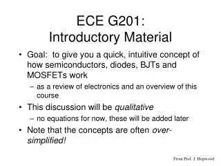
ECE G201:Introductory Material • Goal: to give you a quick, intuitive concept of how semiconductors, diodes, BJTs and MOSFETs work • as a review of electronics and an overview of this course • This discussion will be qualitative • no equations for now, these will be added later • Note that the concepts are often over-simplified! From Prof. J. Hopwood
Semiconductors andPhysical Operation of Diodes Semiconductors Doping n-type material p-type material pn-Junctions forward, reverse, breakdown solar cells, LEDs, capacitance
Periodic Table of Elements Relevant Columns: III IV V
The Silicon Atom 10 core electrons: 1s22s22p6 - - Nucleus: 14 protons 14 neutrons 4 valence electrons - - The 4 valence electrons are responsible for forming covalent bonds
Silicon CrystalEach Si atom has four nearest neighbors — one for each valence electron 0.5 nm
Two-dimensional Picture of Sinote: each line (—) represents a valence electron At T=0 Kelvin, all of the valence electrons are participating in covalent bonds There are no “free” electrons, therefore no current can flow in the silicon INSULATOR Si covalent bond
Silicon at Room Temperature For T>0 K, the silicon atoms vibrate in the lattice. This is what we humans sense as “heat.” Occasionally, the vibrations cause a covalent bond to break and a valence electron is free to move about the silicon.
Silicon at Room Temperature For T>0 K, the silicon atoms vibrate in the lattice. This is what we humans sense as “heat.” Occasionally, the vibrations cause a covalent bond to break and a valence electron is free to move about the silicon. - = free electron -
Silicon at Room Temperature The broken covalent bond site is now missing an electron. This is called a “hole” The hole is a missingnegative charge and has a charge of +1. = a hole - hole +
a bar of silicon * - + I + - V Current Flow in Silicon • Bond breaking • due to: • heat (phonons) • light (photons) • Conductance is • proportional to • the number of • electrons and • holes: • Si resistance • depends on temp. • and light
Some important facts • The number of electrons = the number of holes • that is, n = p in pure silicon • this is called intrinsic material • High temp more electrons/holeslower resistance • Very few electrons/holes at room temperature • n=1.5x10¹⁰ per cm3, but nSi = 5x10²² per cm3 • n/nSi = 3x10-13 (less than 1 in a trillion Si bonds are broken • This is a SEMICONDUCTOR
Important Facts (cont.) • Band Gap: energy required to break a covalent bond and free an electron • Eg = 0.66 eV (germanium) • Eg = 1.12 eV (silicon) • Eg = 3.36 eV (gallium nitride) • Metals have Eg= 0 • very large number of free electronshigh conductance • Insulators have Eg > 5 eV • almost NO free electrons zero conductance
Doping • Intentionally adding impurities to a semiconductor to create more free electrons OR more holes (extrinsic material) • n-type material • more electrons than holes (n>p) • p-type material • more holes than electrons (p>n) • HOW???
Periodic Table of Elements Relevant Columns: III IV V
Si - P n-type siliconadd atoms from column V of the periodic table Column V elements have 5 valence electrons Four of the electrons form covalent bonds with Si, but the 5th electron is unpaired. Because the 5th electron is weakly bound, it almost always breaks away from the P atom This is now a free electron.
VERY IMPORTANT POINT The phosphorus atom has donated an electron to the semiconductor (Column V atoms are called donors) The phosphorus is missing one of its electrons, so it has a positive charge (+1) The phosphorus ion is bound to the silicon, so this +1 charge can’t move! Si - P+ The number of electrons is equal to the number of phos. atoms: n = Nd
Periodic Table of Elements Relevant Columns: III IV V
p-type siliconadd atoms from column III of the periodic table Column III elements have 3 valence electrons that form covalent bonds with Si, but the 4th electron is needed. This 4th electron is taken from the nearby Si=Si bond Si B
p-type siliconadd atoms from column III of the periodic table Column III elements have 3 valence electrons that form covalent bonds with Si, but the 4th electron is needed. This 4th electron is taken from the nearby Si=Si bond This “stolen” electron creates a free hole. Si hole B
VERY IMPORTANT POINT The boron atom has accepted an electron from the semiconductor (Column III atoms are called acceptors) The boron has one extra electron, so it has a negative charge (-1) The boron ion is bound to the silicon, so this -1 charge can’t move! Si + B- The number of holes is equal to the number of boron atoms: p = Na
The pn Junction p-type n-type anode cathode metal silicon oxide doped silicon wafer (chip) integrated circuit diode
Dopant distribution inside a pn junction excess holes diffuse to the n-type region p>>n n>>p excess electrons diffuse to the p-type region
p>>n n>>p - + - + - + Dopant distribution inside a pn junction excess holes diffuse to the n-type region excess electrons diffuse to the p-type region DEPLETION REGION: p~0, and acceptor ions are exposed n~0, and donor ions are exposed + -
p>>n n>>p - + - + x x x - + Voltage in a pn junction charge, r(x) + - electric field, E(x) ~0.7 volts (for Si) voltage, V(x)
p>>n n>>p - + - + x - + Zero Bias voltage, V(x) ~0.7 volts (for Si) At zero bias (vD=0), very few electrons or holes can overcome this built-in voltage barrier of ~ 0.7 volts (and exactly balanced by diffusion) iD = 0
p>>n n>>p - + - + x - + Forward Bias voltage, V(x) 0.65 volts 0.50 volts 0.0 volts vD As the bias (vD), increases toward 0.7V, more electrons and holes can overcome the built-in voltage barrier . iD > 0
p>>n n>>p - + - + x - + Reverse Bias voltage, V(x) 1/2Is 0.0 volts 1/2Is -5 volts Is vD As the bias (vD) becomes negative, the barrier becomes larger. Only electrons and holes due to broken bonds contribute to the diode current. iD = -Is
p>>n n>>p - + - + x - + Breakdown voltage, V(x) large reverse current 0.0 volts -50 volts |I| >> Is vD As the bias (vD) becomes very negative, the barrier becomes larger. Free electrons and holes due to broken bonds are accelerated to high energy (>Eg) and break other covalent bonds – generating more electrons and holes (avalanche).
p>>n n>>p - + - + x - + Solar Cell (Photovoltaic) light voltage, V(x) ~0.7 volts (for Si) Iph Rload Light hitting the depletion region causes a covalent bond to break. The free electron and hole are pushed out of the depletion region by the built-in potential (0.7v).
p>>n n>>p - + - + x - + Light Emitting Diode (LED) photon voltage, V(x) 2.0 volts 1.5 volts 0.0 volts vD In forward bias, an electron and hole collide and self-annihilate in the depletion region. A photon with the gap energy is emitted. Only occurs in some materials (not silicon).
Junction Capacitance p>>n n>>p - + - + - + semiconductor-”insulator”-semiconductor A W n=p~0 e=11.9 The parasitic (unwanted) junction capacitance is Cj = eA/W, where W depends on the bias voltage
Junction Capacitance (Cj) • The junction capacitance must be charged and discharged every time the diode is turned on and off • Transistors are made of pn junctions. The capacitance due to these junctions limits the high frequency performance of transistors • remember, Zc = 1/jwC becomes a short circuit at high frequencies (Zc 0) • this means that a pn junction looks like a short at high f • This is a fundamental principle that limits the performance of all electronic devices