Download
1 / 51
510 likes | 797 Views
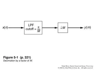
Figure 5-1 (p. 321) Decimation by a factor of M . Figure 5-2 (p. 321) Interpolation by a factor of M . Figure 5-3 (p. 322) First Noble Identity. Figure 5-4 (p. 322) Second Noble Identity,. Figure 5-5 (p. 323) Polyphase structure of a FIR filter with two modifiers.

E N D
Figure 5-5 (p. 323)Polyphase structure of a FIR filter with two modifiers.
Figure 5-6 (p. 324)Polyphase structure of a FIR filter with three subfilters.
Figure 5-7 (p. 325)Polyphase structure of a length-M FIR filter into I parallel subfilters, where K = M/I is an integer.
Figure 5-8 (p. 325)Schemes for sampling rate alteration by a rational factor of I/D.
Figure 5-10 (p. 327)Decimator realization using a polyphase structure.
Figure 5-11 (p. 328)(a) Efficient decimator using a polyphase filter. (b) Noble Identity.
Figure 5-12 (p. 329)Efficient realization of a decimator with linear phase filter in a polyphase structure; D = 3, M = 9.
Figure 5-14 (p. 329)Upsampler followed by a standard polyphase filter.
Figure 5-15 (p. 330)Upsampler followed by a transposed polyphase filter.
Figure 5-16 (p. 330)Efficient structure for interpolation using a transposed polyphase filter.
Figure 5-17 (p. 331)Interpolation using a polyphase filter and a commutator.
Figure 5-18 (p. 332)Interpolator realization using a PTV filter.
Figure 5-19 (p. 334)Narrow band filter design using an interpolated FIR filter.
Figure 5-20 (p. 335) IFIR filter with a factor-of-M interpolation.
Figure 5-21 (p. 325)(a) Standard decimation. (b) IFIR filter with stretch factor M1 followed by ( M2). (c) Two-stage implementation of decimator.
Figure 5-22 (p. 336)IFIT-based decimator design for a factor-of-50 decimator example.
Figure 5-23 (p. 336)(a) Standard interpolator with M = M1M2. (b) Upsampler followed by IFIR filter. (c) Two-stage design of interpolator based on IFIR approach.
Figure 5-25 (p. 337)Decomposition of the spectrum by an analysis filter bank.
Figure 5-27 (p. 338)A uniform subband coding and decoding scheme using filter banks.
Figure 5-28 (p. 339) (a) A three-level multiresolution subband coder. (b) Decomposition of the frequency spectrum.
Figure 5-29 (p. 339)A three-level multiresolution subband decoder.
Figure 5-30 (p. 341)A uniform DFT filter bank; inefficient realization.
Figure 5-31 (p. 343)A uniform DFT filter bank implemented using a polyphase structure and IDFT.
Figure 5-32 (p. 343) Efficient realization of a uniform DFT filter bank.
Figure 5-33 (p. 344)2-channel QMF bank with channel degradations.
Figure 5-34 (p. 345)2-channel QMF bank with no channel distortion.
Figure 5-35 (p. 345)Magnitude responses for the analysis filters; (a) nonoverlapping and (b) overlapping.
Figure 5-36 (p. 349)Polyphase QMF bank; (a) analysis bank and (b) synthesis bank.
Figure 5-37 (p. 350)Complete QMF bank in polyphase form; efficient realization.
Figure 5-38a (p. 351)(a) Impulse response of the 48D Johnston filter.
Figure 5-38b (p.352) (b) Magnitude responses of filters H0(z).
Figure 5-38c (p. 352)(c) 10 log10 (|H0()|2 + |H1()|2) for the design example using the Croisier-Esteban-Galand filter bank and the Johnston 48D filter.
Figure 5-39 (p. 355)Relationship among filters in a Smith-Barnwell QMF bank.
Figure 5-40 (p. 356)Magnitude response of half-band filter showing symmetry about /2.
Figure 5-41 (p. 357)Zero locations of (z) and H0(z) for the design example of a Smith-Barnwell filter bank.
Figure 5-42 (p. 358)Magnitude responses of all filters for the design example of a Smith-Barnwell filter bank.