Download
1 / 82
840 likes | 1.07k Views
Dr. HABEEB HATTAB HABEEB Office: BN-Block, Level-3, Room-088 Email: hbuni61@yahoo.com Ext. No.: 7292. U niversity TENAGA National College Of Engineering Mechanical Department. Lecture Note. Computer Aided Manufacturing. CAM.

E N D
Dr. HABEEB HATTAB HABEEB Office: BN-Block, Level-3, Room-088 Email: hbuni61@yahoo.com Ext. No.: 7292 Lecturer: Dr. HABEEB ALANI
University TENAGA National College Of EngineeringMechanical Department Lecture Note Lecturer: Dr. HABEEB ALANI
Computer Aided Manufacturing CAM Lecturer: Dr. HABEEB ALANI University TENAGA Nasional Lecturer: Habeeb Al-Ani
Overview • Computer Aided Manufacturing Defined • Brainstorming Exercise • CAM activities • How It Works • Summary • Conclusion Lecturer: Dr. HABEEB ALANI
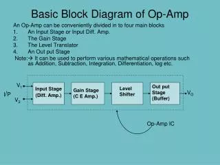
Computer Aided Manufacturing • What is Computer Aided Manufacturing? • It is “control of the manufacturing process by computers” involving the integration of CAD engineering data and the computerized equipment which manufactures the product. Lecturer: Dr. HABEEB ALANI
Computer Aided Manufacturing • Other definitions: • “Computer aided manufacturing concerns the use of algorithms for planning and controlling fabrication processes.” • Computer aided manufacturing is “the use of computers for managing manufacturing processes.” Lecturer: Dr. HABEEB ALANI
Computer Aided Manufacturing • Using technology to produce • Leveraging capital investments • Increasing productivity through automation • Decreasing lead time through programming and controlled machinery Lecturer: Dr. HABEEB ALANI
Brainstorming Exercise • How can CAM benefit your company? • Integrate design and manufacturing • Make mass customization possible • Reduce costs • Leverage computing power • Automate manufacturing processes Lecturer: Dr. HABEEB ALANI
Brainstorming Exercise • Identify benefits and costs of CAM: • Direct Benefits • Indirect Benefits • Tangible Costs • Intangible Costs Lecturer: Dr. HABEEB ALANI
Brainstorming Exercise • What processes in your company could be more efficient through CAM? Lecturer: Dr. HABEEB ALANI
CAM activities • Essentially the collection of computer technologies used in manufacturing • Computer Numerical Control (CNC) • Direct Numerical Control (DNC) • Flexible Manufacturing System (FMS) • Robots • Automated material Handling Systems Lecturer: Dr. HABEEB ALANI
CAM activities • Computer Numerically Controlled (CNC) • Machine that is controlled by computer • Utilizes monitor and keyboard for operator interaction • Facilitates greater control over quality • Allows machine to monitor the maintenance of its parts Lecturer: Dr. HABEEB ALANI
CAM activities • Direct Numerical Control (DNC) • Each machine contains own microprocessor • Entire bank of machines controlled by a single central computer • If used with automated material handling, considered to be a flexible manufacturing system Lecturer: Dr. HABEEB ALANI
CAM activities • Direct Numerical Control (DNC)
CAM activities • Direct Numerical Control (DNC)
CAM activities • Flexible Manufacturing System (FMS) • Numerous computer-controlled machines fed by automated material handling system • Allows for broad and deep product mix • Minimal setup times enable small lot sizes Lecturer: Dr. HABEEB ALANI
CAM activities • Robots • Mechanical manipulators that can be accessed with programming method • Consistent, repetitive-motion tolerant • Ideal for tasks that are hazardous to humans Lecturer: Dr. HABEEB ALANI
CAM activities • Automated Materials Handling System • System where raw materials are automatically fed into machines • Examples: • Conveyor belts • Automated Guided Vehicles (AGV) • Automated Storage and Retrieval Systems (ASRS) Lecturer: Dr. HABEEB ALANI
How It Works • Product is conceived by engineer • Product is designed using CAD software • CAD data is transferred to manufacturing machine’s memory • Machine uses the CAD data to produce the product, with little human intervention Lecturer: Dr. HABEEB ALANI
How It Works • Old System (without CAM) • Product is designed with CAD software • Each production machine is programmed individually OR – if not automated : • Employees are trained on proper production of the product Lecturer: Dr. HABEEB ALANI
How It Works • New System (using CAM) • Product is designed with CAD software • Product specifications are sent over the plant network to each machine • Machines have ‘intelligence’ to produce the products without human intervention Lecturer: Dr. HABEEB ALANI
CAM solution: • Enables faster turnaround of new products • Reduces waste by using raw materials more efficiently • Generates costs based on design specifications Lecturer: Dr. HABEEB ALANI
Summary • Here’s what we’ve looked at so far…. • Definition • Brainstormed • CAM activities • How It Works • CAM solution Lecturer: Dr. HABEEB ALANI
Conclusion • CAM enables companies to leverage capital investment • CAM allows for cost savings that can be passed on to the final consumer • CAM utilizes human resources more efficiently to minimize labor costs Lecturer: Dr. HABEEB ALANI
Remember&rememberX 1000 If you want to be part of a profession dedicated to quality and continuous improvement, consider CAM as your career of choice… Lecturer: Dr. HABEEB ALANI
THANK YOU HABEEB Lecturer: Dr. HABEEB ALANI
CAM Systems & CNC Machine Lecturer: Dr. HABEEB ALANI
History 1955 - John Parsons and US Air Force define a need to develop a machine tool capable of machining complex and close tolerance aircraft parts with the same quality time after time. MIT is the subcontractor and builds the machine for the project. Lecturer: Dr. HABEEB ALANI
History: Continued 1959 - MIT announces Automatic Programmed Tools (APT) programming language 1960 - Direct Numerical Control (DNC). This eliminates paper tape punch programs and allows programmers to send files directly to machine tools Lecturer: Dr. HABEEB ALANI
History: Continued 1968 - Kearney & Trecker machine tool builders market first machining center 1970’s - CNC machine tools & Distributed Numerical Control 1980’s - Graphics based CAM systems introduced. Unix and PC based systems available Lecturer: Dr. HABEEB ALANI
History: Continued 1990’s - Price drop in CNC technology 1997 - PC- Windows/NT based “Open Modular Architecture Control (OMAC)” systems introduced to replace “firmware” controllers. Lecturer: Dr. HABEEB ALANI
Control Systems Open-Loop Control Stepper motor system Current pulses sent from control unit to motor Each pulse results in a finite amount of revolution of the motor001” is possible
Control Systems Open-Loop Limitations Control unit “assumes” desired position is achieved No positioning compensation Typically, a lower torque motor Open-Loop Advantages Less complex, Less costly, and lower maintenance costs Lecturer: Dr. HABEEB ALANI
Control Systems Closed-Loop Control Variable DC motors - Servos Positioning sensors -Resolvers Feedback to control unit Position information compared to target location Location errors corrected
Control Systems Closed-Loop Advantages DC motors have the ability to reverse instantly to adjust for position error Error compensation allows for greater positional accuracy (.0001”) DC motors have higher torque ranges.. stepper motors Lecturer: Dr. HABEEB ALANI
Control Systems Closed-loop limitations Cost Lecturer: Dr. HABEEB ALANI
Three Basic Categories of Motion Systems Point to Point - No contouring capability Straight cut control - one axis motion at a time is controlled for machining Contouring - multiple axis’s controlled simultaneously Lecturer: Dr. HABEEB ALANI
Three Basic Categories of Motion Systems Lecturer: Dr. HABEEB ALANI
CNC - NC Machine Tools Computer Numerical Control (CNC) - A numerical control system in which the data handling, control sequences, and response to input is determined by an on-board computer system at the machine tool. Lecturer: Dr. HABEEB ALANI
CNC Advantages Increased Program storage capability at the machine tool Program editing at the machine tool Control systems upgrades possible Option -resident CAM system at machine tool Tool path verification Lecturer: Dr. HABEEB ALANI
Machining Centers Machine motion is programmable Servo motors drive feed mechanisms for tool axis’s Positioning feedback is provided by resolvers to the control system Lecturer: Dr. HABEEB ALANI
NC Numerical Control (NC) - A control system which primarily processes numeric input. Limited programming capability at the machine tool. Limited logic beyond direct input. These types of systems are referred to as “hardwire controls” and were popular from the 1950’s to 1970’s. Lecturer: Dr. HABEEB ALANI
Machining Centers A machining center can be defined as a machine tool capable of: Multiple operation and processes in a single set-up utilizing multiple axis Typically has an automatic mechanism to change tools Lecturer: Dr. HABEEB ALANI
Machining Centers Example - A turning center capable of OD turning, external treading, cross-hole drilling, engraving, and milling. All in machining is accomplished in one “set-up.” Machine may have multiple spindles. Lecturer: Dr. HABEEB ALANI
Programming Methods-APT Developed as a joint effort between the aerospace industry, MIT, and the US Airforce Still used today and accounts for about 5 -10% of all programming in the defense and aerospace industries Lecturer: Dr. HABEEB ALANI
Machining Centers Lecturer: Dr. HABEEB ALANI
Programming Methods Automatically Programmed Tools (APT) A text based system in which a programmer defines a series of lines, arcs, and points which define the overall part geometry locations. These features are then used to generate a cutter location (CL) file. Lecturer: Dr. HABEEB ALANI
Programming Methods-APT Requires excellent 3D visualization skills Capable of generating machine code for complicated part programs 5 axis machine tools Lecturer: Dr. HABEEB ALANI
Programming Methods-APT Part definition P1=Point/12,20,0 C1=Circle/Center,P1,Radius,3 LN1=Line/C1. ATANGL,90 Cutter Commands TLRT,GORT/LN1.TANTO,C1 GOFWD/C1,TANTO,L5 Lecturer: Dr. HABEEB ALANI
Programming Methods-CAM Computer Aided Machining (CAM) Systems Graphic representation of the part PC based Integrated CAD/CAM functionality “Some” built-in expertise Speed & feed data based on material and tool specifications Lecturer: Dr. HABEEB ALANI