Download
1 / 20
200 likes | 377 Views
Module 5.0: Internetworking & Network Layer. Basic concepts Congestion Control Routing Protocols Flooding Source routing Distance vector routing Link state routing Routing for VC Routers vs. Switches. Chapters: 19,20,21,22. Concepts.

E N D
Module 5.0: Internetworking & Network Layer • Basic concepts • Congestion Control • Routing Protocols • Flooding • Source routing • Distance vector routing • Link state routing • Routing for VC • Routers vs. Switches Chapters: 19,20,21,22 K. Salah
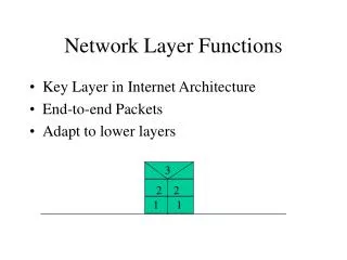
Concepts • Internetworking refers to a collection of interconnected networks that function as a singe network. • Internetwork is abbreviated as internet. However, Internet refers to the world’s largest internetwork. • Network layer performs: • Provides services to Layer 4 (Transport) including fragmentation and re-assembly • Performs congestion control • End-to-end routing K. Salah
Congestion Control • Congestion occurs when the number of packets being transmitted through the network approaches the packet handling capacity of the network • Congestion control aims to keep number of packets below level at which performance falls off dramatically • Data network is a network of queues • Generally 80% utilization is critical • Finite queues mean data may be lost • Packets arriving are stored at input buffers • Routing decision made • Packet moves to output buffer • Packets queued for output transmitted as fast as possible • Statistical time division multiplexing • If packets arrive too fast to be routed, or to be output, buffers will fill. And packets will be discarded K. Salah
Congestion Control • When packets are discarded, the sources must retransmit these packets, in addition to a new packets. This will increase the load on the network and more buffers become saturated. Even if a packet makes it through, by that time, the upper layer times out. Under these circumstances, the throughput becomes zero. • Not the same as flow control. Flow control applies only to point-to-point traffic. Flow control affects congestion. Congestion has a global scope. • Mechanisms of congestion control: • Backpressue • Send choke packet hop-by-hop • Choke packet • Send choke packet to source • Implicit congestion signaling • Source slows down if packets are discarded or delayed • Explicit congestion signaling • Binary based: A bit set in a packet indicates congestion • Credit based: Indicates how many packets source may send • Rate based: Supply explicit data rate limit, e.g. ATM. K. Salah
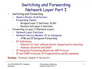
Routing Protocols • Routing protocols perform two primary functions: • Determine the “best” path • Maintain a routing table • Routing algorithms are used to calculate the least-cost path from source to destination. • Common cost metrics • Hops (the number of routers in the path) • Propagation delay • Bandwidth • Time • Channel utilization • Two general algorithms • Distance Vector Routing • Link State Routing • Other routing protocols • Flooding • Source Routing K. Salah
Flooding • The principle says a router forward an incoming packet to all ports except the one the packet came through. • Effective method: • At startup to build routing table • Survivability (military networks). • Can drag down the network: • TTL • Each switch adds its id to packet before it floods it K. Salah
Source Routing • Does not require intermediate node routing • Sender must specify the entire route • Sender uses router discovery at initialization. Intermediate nodes use flooding. • At intermediate nodes, the header is examined, strips off the label identifying the node, and forward to the next node. K. Salah
Distance Vector Routing • Each router periodically shares its knowledge about the entire network with its neighbors. • Knowledge about the whole network: Each router sends its accumulated knowledge about the entire network to its neighbors. This knowledge is sparse at the beginning. • Routing only to neighbors: Each router sends periodically knowledge to those routers that has directed links. Neighboring routers use this information to update their own knowledge. • Information sharing at regular intervals: Every 30 seconds, Each router sends its knowledge to neighboring routers, regardless of any changes. • Distance vector algorithm adapts to changes in network topology gradually as the information on the changes percolates through the network. K. Salah
Example K. Salah
Routing Table Original routing tables. Next hop field is empty initially. K. Salah
Updating routing table for router A Final routing tables K. Salah
An Example of updating routing table • Distance vector is based on “Bellman-Ford” algorithm to find the next hop that yields the shortest distance to destination. K. Salah
Link State Routing • Each router shares its knowledge of its neighborhood with all routers in the internetwork. • Knowledge about the neighborhood: Router sends information about the neighborhood only, not the entire table. • To all routers: Such information propagates from router to router, using flooding. Eventually every router receives a copy of the same information. • Information sharing when there is a change: Each router sends out information about the neighbors when there is a change. • In link state routing, eventually each router is able to construct a map of the entire network and from this map the best route is found. K. Salah
Link state packet (LSP) • Cost is an outbound cost and set by the router. • A router gets information about its neighbors by periodically sending them a short greeting message, thus determining the cost and Neighbor for the LSP. K. Salah
Link state database Flooding of A’s LSP • Because every router receives the same LSPs, every router builds the same database. • This database is used to calculate the routing table, by applying Dijkstra algorithm. K. Salah
The Dijkastra Shortest Path First (SPF) Algorithm • The algorithm uses the “closest nodes” concept and is based on the following principle: “Give a source node, n, the shortest path from n to the next closest node, s, either (a) is a path that directly connects n to s or (b) includes a path containing n and any of the previously found intermediate closest nodes plus a direct link from the last intermediate closest node of this path to s”. Routing table for router A K. Salah
Routing for VC • Virtual Circuit network with 3 VCs • A to B with VCI 1 • A to D with VCI 5 • C to B with VCI 6 • Using local VCI over global VCI • Searching for available VCI is not simple K. Salah
Routing tables for the previous network at intermediate nodes • Used in ATM networks. ATM uses link-state routing to find the best route to construct its routing table. K. Salah
Most Popular Routing Protocols • OSPF* (Open Shortest Path First) • Link-state, interior, 50 routers per area, about 100 areas, • RIP v1* (Routing Information Protocol, version 1) • Distance-vector, interior, 15 hops • RIP v2* (Routing Information Protocol, version 2) • Distance-vector, interior, 15 hops • BGP* (Border Gateway Protocol) • Path-vector, exterior, thousands of routers • EIGRP+ (Enhanced Interior Gateway Routing Protocol) • Advanced distance-vector, interior, thousands of routers • IGRP+ (Interior Gateway Routing Protocol) • Distance-vector, interior, 255 hops • IS-ISx (Intermediate System to Intermediate System) • Link-state, interior, thousands of routers * Defined by IETF + Defined by Cisco x Defined y OSI K. Salah
Routers vs. Switches • The primary difference is one semantics. Switches historically infer CO links; routers use CL links. Traditionally, routers have performed router table lookups and packet forwarding in software. • Layer-2 Switches start having routing functionality, and Layer-3 routers start having ASIC (Application Specific Integrated Circuit) switching technology for packets. • Layers 2 and 3 are merging and it is becoming difficult to distinguish between switches and routers. • Layer 3 or IP switching: routing IP packets in ASIC, e.g, MPLS. • Layer 4/7 switching is a new and emerging area, called information content switching. • Layer 4: direct all traffic based on TCP destination port. • All traffic with destination TCP port 80, is directed to a switch port where a web cache resides. • Layer 7: direct traffic based on information used in the payload. • Examine URL GET request. If request for image, direct it request to an optimized image server port. K. Salah