Download
1 / 58
620 likes | 847 Views
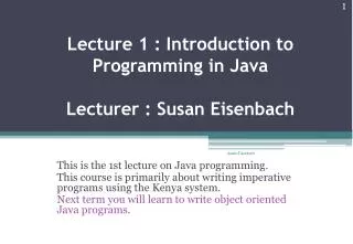
Lecture 10 Buses, CPU and I/O System. Pradondet Nilagupta Spring 2000. Buses, CPU and I/O System. HSA - hardware system architecture Specifies the structural characteristics: organization of hardware elements performance

E N D
Lecture 10 Buses, CPU and I/O System Pradondet Nilagupta Spring 2000
Buses, CPU and I/O System • HSA - hardware system architecture • Specifies the structural characteristics: • organization of hardware elements • performance • We will look at the Bus architecture, CPU and I/O System and how all of these components work together to execute program instructions
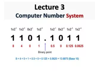
BUSES • Move Info between components of the computer. • Information can be: • Control signals (control bus) • Data and program instructions (data bus) • Addresses (address bus) • Composed of a set of wires that allow current to flow between components. • 1 wire = 1 bit, 8 wires for 1 byte, typical sizes are powers of 2 such as 8, 16, 32
Type of Buses • Local Buses • Address buses • Data buses • Control buses • System Buses • Bus controller • Arbiter • Expand Local Buses
Local Buses LOCAL BUSES • The simplest buses consist of set of wires • The buses are local buses because they are part of the device that uses and controls them. Address buses • tend to be specialized in purpose • usually unidirectional • most frequently transfer addresses from the program counter (PC), stack, or address-computation circuitry to memory
Local Buses Data Buses • tend to be more general in purpose • bidirectional • carry data, instruction s, and also addresses to and from main memory system , attatched I/O devices, and the ALU Control Buses • carry signals from the control unit to other components of the computer and back to the control unit
System Buses • independent components of the computer used to connect devices together controlled by its own controller • has its own control circuit, called a bus controller, and within each bus controller is an arbitrer which process to use the bus • tend to have well-documented and stable definitions so that designer can attach a wide variety of devices to them • ex. DEC UNIBUS, S-100 Bus, Apple NuBus
Address Lines Bus Controller Data Lines } Bus-grant lines Bus Arbiter } Bus-request Line Device 1 Device 2 Typical system bus with two attached devices
Bus Controller Bus Arbiter A CPU Bus and Expaned Local Bus } Control Lines Address Lines Data Lines } Bus-grant lines } Bus-request Line Device 2 Device 1 CPU
Expanded local Buses • found mostly in PCs, these are local buses with extensions for devices outside of the CPU. • similar to system buses except that the CPU’s clock and timing circuits regulate them. • processors-specific • flexible operationally and provide a platform for system expansion. • ex. IBM PC I/O Channel Bus and IBM Micro Channel Architecture (MCA)
Bus Transfers and Control Signals • Bus Transfer - transmission of one or more items across the bus. Each type of transmission is called a bus cycle • Bus cycle types include: memory read, memory write, I/O read, I/O write, interrupt • Bus states - transfers that occur in stages • Bus cycle consists of well-defined sequence of bus states. • Clock regulates bus states
Bus Control Signals • Bus masters are the devices that can use the system buses. A device must first have permission to use the bus from the bus arbiter. • Slaves are passive devices which respond to requests from the bus master, e.g. main memory • Devices are connected to bus arbiter by Bus-request line. Device sends Bus-request signal to arbiter and receive accept-signal over bus-grant line
Typical read cycle using an Expanded Local Bus CPU sends read request and address-enable signal via the control bus and address via address bus Address Bus CPU } Data Bus The CPU sends R, AEN, and the address to the storage system Local Bus Control Bus R W AEN R W AEN Storage System
Typical read cycle using an Expanded Local Bus Storage system receives request and address and decodes the address Address Bus CPU Data Bus Control Bus R W AEN R W AEN The storage system decodes the control signals and retrives the required datum
Typical read cycle using an Expanded Local Bus storage sends back requested datum along data bus Address Bus CPU Data Bus Control Bus R W AEN R W AEN The storage system places the recalled datum on the data bus
CPU • Central Processing Unit (also called the processor or the microprocessor in PCs) • Consists of • Register set • ALU (series of hardware circuits for performing the arithmetic, logic and shift operations) • Control Unit
ALU • Functional units - hardware elements that perform arithmetic, logic and shift ops • Some computers have multiple independent functional units, others have a single functional unit. Whichever, these make up the ALU. • Includes a register for temporary storage, flags/status register, and multiplexor to select appropriate hardware circuit.
ALU of Simple computer ALU ALU data input bus Arithmetic and logic circuitry Shifter Control signals (from control unit) control control Status signals (to control unit) Multiplexor C V N Z control Flags control temporary register ALU data output bus control
More on the ALU • Some computers use a math-coprocessor to perform floating point operations. • RISC computers use two or three independent functional units in performing some operations such as branch processing and floating-point operations. • Cray computers have many independent functional units for paralellism. Other architectures use pipelining of functional units
Control Unit • Fetch from memory the next instruction, place it into the IR and increment the PC • Decode instruction and execute it • Decoding actually means decoding the instruction into a microinstruction or into microorders, control signals sent to various hardware elements (such as ALU components, registers, bus arbiter, etc…)
current inst next inst IR Addr generation Control unit PC Operational Register ALU A simple Von Neumann machine Main Memory A program Address bus Data Bus CPU
current inst next inst During Fetch Cycle Main Memory A program Address bus 1 Data Bus IR Addr generation Control unit 2 PC Operational Register ALU CPU
Type of Control Units • Microprogrammed - most computers built during the 1970’s and 1980’s have this type where the computer architect programs the microinstructions for each machine language instruction. • Conventional (or hard-wired) - used in high-performance and RISC computers, as the name implies, the microinstructions are hard-wired into the computer. This is much faster but much less flexible.
Microprogram • IR stores current machine language instruction from program in main memory • Each machine instruction is represented as a series of microinstructions, in the Control Store • MicroPC points to the appropriate location of the current microinstruction in the Control Store • Executing a machine instruction requires finding the microinstructions and executing them until the microinstruction has completed
Address computation circuitry mPC Control Store IR C INC EN C m instruction buffer C CL 1 2 3 4 m instruction decoder 5 6 7 8 Sequencer 9 10 Main Component of Microprogrammed control unit Status bits Internal Address bus Microorder Control and Clock inputs
Ordinary Operation • Sequencer causes address of current machine instruction to be placed in microPC • It may also clear the microinstruction buffer • Sequencer initiates control-store read and transfers microinstruction to microinstruction buffer
Ordinary Operation • Microinstruction decoder decodes microinstruction into microorders and issues those orders over control lines • If a non-branching microinstruction, then microPC is incremented, otherwise new address in control store is calculated and placed in microPC
Organization of Microprogram • Each Machine Language operation is actually a sequence of microinstructions • Each of these microprograms is placed in the control store • Included are the microprograms for instruction fetch, interrupt intiation and other routines separate from machine language instructions
One organization for microcode in a control store Control Store A0 Microcode for op code 0 A1 Microcode for op code 1 Microcode for op code n An AIF Microcode for instruction fetch Microcode for interrupt initiation AII Other Microcode
Branching/Non-Branching • Branching microinstructions hold the branch address inside of the microinstruction itself. • Branching occurs only within the Control Store (as opposed to a machine language branch to another location in main memory) • Special bit designates whether a microinstruction is a branch or nonbranch.
Branching/Non-Branching • Internal Address Bus is used to compute new control store location • Nonbranching instructions require that the microPC be incremented
Machine Startup • Instead of the ordinary operation, at machine startup, a special routine occurs: • Registers are initialized • A hardware-generated address found in the reset-vector is moved into the microPC or indirect address is used to find the address to be moved into the microPC
Main Memory Initial program First Instruction PC Reset vector (hardware generated) using a hardware-generated reset vector Machine Startup
First Instruction Machine Startup Main Memory Reset vector PC Initial program Reset vector (hardware generated) using a hardware-generated reset vector address
Microinstruction forms • Microinstructions are simply a list of control orders for the various buses and gates in the computer (predominantly in the CPU) • Horizontal Control - each microinstruction is a series of bits (perhaps 50-150), each of which represents a single control line
Microinstruction Forms • Vertical Control - groups of bits in the microinstruction represent commands. This requires decoding or demultiplexing before the control commands can be issued • Horizontal is faster but requires greater lengthed microinstructions
Control unit microorders Individual microorders Microinstruction Branch address Horizontal Control microinstruction
Decoder Decoder Decoder Microinstruction Branch address Vertical control microinstruction using decoder Control unit microorders Individual microorders
Examples of Microprogramming • Instruction Fetch • Fetch instruction from memory: • Place Content of PC on the A-bus (1D) • Enable memory to D-bus (MD) • Signal read operation (RM) • Transfer value to the IR (CI) • Increment PC (IP) • Branch to Microprogram instruction (1 in bits 0 and 16) • 00000100001000001100 • 00000000000010000000 • 00010000000000000001
Complement value in accumulator • Perform NOT operation • Send signal to functional unit to perform NOT (101) • Transfer result into X (CX) • Instruct functional unit to send X to D-bus (UD) • Transfer result to Accumulator (CA) • Branch to fetch microprogram • 10100011010000000000 • 000--------------001 where --…-- is the location of fetch
ADD operand from Mem. to Accumulator • Perform the Add • Send address field of IR to the A-bus (IA) • Signal read-memory operation (RM) • Send data from memory to D-bus (MD) and onto the functional unit - might take some time • Instruciton functional unit to peform add (001) • Store result • Send functional unit result to D-bus (UD) • Store result in Accumulator (CA) • Branch to fetch microprogram
Conventional Units • Alternative to microprogrammed control is to hardware the control, that is, each machine language instruction causes the control unit to send out its sequenced control commands directly. • Used in supercomputers and some RISC computers. Must faster performance.
Conventional Units • Some computers combine both approaches, using conventional units for arithmetic types of instructions. • Outcome is the same whether using Conventional or Microprogrammed Control.
Exception Processing • Exceptions - branches initiated by hardware (interrupts) or program (traps). • Interrupts are asynchronous (computer’s clock does not control them, instead other devices such as I/O devices control them) • Traps are synchronous - examples include arithmetic overflow, memory protection violation or illegal op code.
Exception Processing Hardware • Preserve processor context (registers values) by saving onto special hardware (e.g. save area in memory or a stack) • Branch to exception handling code (which may cause additional info to be saved such as parts of main memory) • After exception handling terminates, restore state from stack and continue normal execution • Special instructions are usually available such as RETURN FROM INTERRUPT which restores state
Priority Exceptions • Priority Exceptions - exceptions may arise from more than one source. Exceptions are often prioritized so that lower priority exceptions may be disabled while handling higher priority exceptions. • If a device requests an interrupt, it sets a flag in the Interrupt Code Register. A priority encoder selects the highest priority interrupt and the interrupt disabled flip-flop is set to disallow further interrupts.
Interrupt Polling • Once an exception is raised, the hardware must determine the appropriate exception handler and determine which device raised the exception. • Interrupt polling is used to determine which device raised the interrupt. An alternative is to have an interrupting device place a designation code in a register.
Interrupt Polling • The correct exception-handler is determined by searching the exception-vector-table for the starting address of the given exception (which can be determined by finding what flag(s) was set in the ICR. • Placing this new address in the PC causes a branch to the exception handler.
Exception Masking • Rather than disabled all interrupts, an exception at one level of priority may wish to disable all exceptions at a lower level of priority. • Exception masking allows higher priority exceptions to interrupt the current exception but causes lower priority exceptions to wait until the current exception terminates. • An Interrupt Mask Register is used to disable lower priority exceptions.
I/O System • Set of all I/O devices in the computer system including physical devices and I/O interface devices • In the early days of computers, I/O devices were limited to line printer, punch card reader. Today there are numerous types of I/O devices (terminal, mouse, scanner, etc…) • CPU-controlled I/O - the CPU would interrupt its current process to directly handle all I/O. I/O commands were Write A to Device N, Read A from Device N and possibly Test Device N.