CPU Design Project
This project outlines the design of a multi-cycle, 16-bit processor focusing on an Intel-style instruction set architecture. It features 16 registers, including general-purpose and specific purpose registers (such as stack pointer and instruction pointer). The processor supports a variety of instructions for data movement, arithmetic operations, bitwise operations, and flow control, with a detailed implementation of pseudo-instructions. A finite-state machine in the control unit manages the processor's operations, maintaining internal flags for enhanced conduct of arithmetic and logical operations.


CPU Design Project
E N D
Presentation Transcript
CPU Design Project • Christopher Brown • Fall 2010, ELEC 5200
Overview • Multi-cycle processor • 16-bit instructions • 16 registers • Intel-style instruction set
Registers • AT - Assembler Temporary • NULL - Readonly, always 0x0000 • FULL - Readonly, always 0xFFFF • R0 to R6 - General purpose, maintained across subroutines • T0 to T3 - General purpose, not maintained across subroutines • SP - Stack pointer, for use with pseudo-instructions such as push and pop • IP - Instruction pointer, always points to the next instruction
Instruction Set • Jumps - JMP, JG, JNLE, JGE, JNL, JL, JNGE, JLE, JNG, JE, JNE • Memory - MOV • Arithmetic - ADD, SUB • Bitwise - XOR, AND, OR • Other - NOP, HLT
Jumps • 8-bit relative operand • Flow determined by Sign, Ovrflw, and Zero control flags • 11 varieties: • 1 unconditional • 6 conditional • 4 pseudo
Memory • Uses register indirect addressing only • MOV (srcR), destR • Loads the contents of memory at the address stored in srcR to the register specified by destR. • MOV srcR, (destR) • Stores the contents of srcR to the memory address stored in destR.
Arithmetic • ADD and SUB • 2 variants of each • ADD/SUB regR, destR • Add or subtract the contents of regR from destR, storing the result in destR. • ADD/SUB immed8, destR • Add or subtract immed8 from destR, storing the result in destR. • Updates Sign, Ovrflw, and Zero control flags.
Bitwise • XOR, AND, and OR • XOR/AND/OR regR, destR • Performs a binary operation between regR and destR, storing the result in destR. • Updates Sign and Zero control flags.
Other • NOP • It does nothing. • HLT • Puts the control unit into a halted state • The only way to continue execution is through a reset
Pseudo-Instructions • PUSH regR • SUB 1, SP • MOV regR, (SP) • POP regR • MOV (SP), regR • ADD 1, SP • RET • MOV (SP), IP ; POP IP • ADD 1, SP • CALL relM8XOR AT, ATADD IP, ATADD 4, ATSUB 1, SP ; PUSH ATMOV AT, (SP)JMP relM8
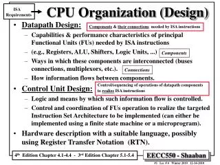
Control Unit • Finite-state-machine • Moore machine - Outputs depend solely on the current state • 8 unique states • Also maintains 3 internal flags: Sign, Ovrflw, and Zero