Download
1 / 15
150 likes | 258 Views
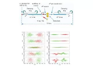
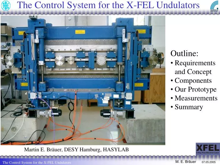
The Control System for the X-FEL Undulators. Outline: Requirements and Concept Components Our Prototype Measurements Summary. Martin E. Bräuer, DESY Hamburg, HASYLAB. Requirements and Concept. synchronized gap movements comprise the modular setup => cells high reliability

E N D
The Control System for the X-FEL Undulators • Outline: • Requirements and Concept • Components • Our Prototype • Measurements • Summary Martin E. Bräuer, DESY Hamburg, HASYLAB
Requirements and Concept • synchronized gap movements • comprise the modular setup => cells • high reliability • allow complex movement-schemes • movements with high dynamics • long-term availability of components • Segment: • 4 synchronized motors • gap: ≤ 1µm precision • single-motor operation (“taper”) • speed: (0,02 .. 20)mm/s • force: ≤ 160kN • Intersection: • ≤ 5 control variables (i.e.: position, current..) • value: f(gap) • synchronized: ≤ 10 µm gap • cycle-time: ≤ 5 ms Cell Segment Intersection cell i-1 cell i
.. complex movements Taper-mode: Diagnostics: Have ≥1 device switched-on at a time => Move quickly (>30 devices in an undulator!) Various “patterns” need maximum flexibility !
Industrial components • Industrial Controls: • robust • productivity • fast markets (10y = an age !) • cheap • a huge market: O(200) German companies & • safe • Secure investments: • Truly open standards (CANopen, SERCOS, RS232, EtherCAT) • Vendor independent • Multi-Vendor environments
Motors 1/1 step Servo-controller position velocity current fieldbus 1/2 step ? ? encoder ? 1/4 step encoder 1kW ! 1€ 1/8 step 1/16 step 1/32 step 1/64 step • From the automation market • 300 .. 1000000 W • Cheap, robust, well understood Stepper • Rotating magnets • Static coils Synchron-Servo-Motor: Servo: Measure the rotor angle Stepper: Assume a rotor following
Encoder Systems Measure the linear position of each axis =>The encoder determine the accuracy/resolution • Operating them ‘close’ to a beam • Singular point of precision • Mounting? • ULE (ZERODUR-like) mountings => compensate thermal deviations • Open, incremental encoders => reference-switch/mark needed • Optical reading of a ribbon • 20µm period length => sin,cos Signal @ 1Vpp • Electronic “oversampling” (x4096) => linear “steps” • Resolution: ok, precision?
Control-System high resolution encoder cell i motors (general network) (multiturn) rotational encoder real-time network local control CPU … … motor controller and amplifier Intersection (SERCOS drives for Intersection) prec. analog out I/O signals (fieldbus-devices incell(opt.) coils Dezentral periphery motors (i.e. stepper) Intersection not fully defined need maximal flexibility
Safety issues • Needed feature in industrial solutions • Bus sensitive to many errors • Robustness (no false alarms required (HERA!) • Additional measures allways possible • Axis synchronization has a high priority in commercial systems • “It is all software” • Yes, get this from professionals! • We have to define procedures • No problems found yet • Commissioning phase “interesting” • Have to foresee a indiv. Taper • Several devices will be used in Petra III Interlocks Personal-safety Radiation safety To be defined later.. Total: 4x 132kW
Hardware Details Terminals: IO and Intersection 4x PWM output 4x 0..10v (0.01% prec.) 4x stepper (one mounted) 12mm Power / safety CPU Controller / amplifier
Measured Data: Precision Encoder vs. Motor 1 Rotor (incl. offset to get picture) pos = gap/2 [mm] 0.5µm tsample = 1ms 1 Axis and master (thin) Time [s]
Measured Data: Precision Encoder vs. Motor 2 Encoders & servo-loops: loose requirements on mechanics 150µm ! one bad spindle (known) Rotors (incl. offset to get picture) 50µm 4 Axis and master
First stress tests 0.5µm High precision – with 137mm ‘walk’ one axis all axis
First stress tests 0.5µm 17x open/close cycles with highest speed v: 272mm in 12.5s
Summary • First electro-mechanical prototype working • System got up successfully (HarWi / MTU still there) • Found a good supplier • Measurements ongoing • No showstoppers found yet • The control system can be used rather widely Outlook New fieldbus: EtherCAT: • >10x faster than Profibus • Based on ethernet • Existing (support/interest by >170 companies) • Open (fully documented) • Have only 1 bus ! • > 50µs tasks with I/O, 12000 dig. IO in 350µs, 100 Servos-Axis in 100µs