OrCad Release 9.2
430 likes | 931 Views
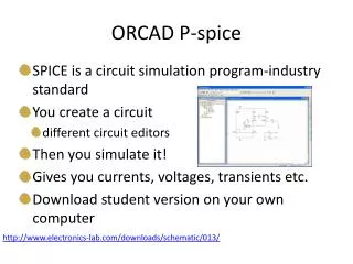
OrCad Release 9.2. For Slide show 1. The Objective. Open and Save New Design File Create a Circuit Schematic Get Place, Place Parts i.e. Resistors and Sources Edit Part Values i.e. Resistors and Sources. The Schematic. OrCad . Adding Parts to a schematic.

OrCad Release 9.2
E N D
Presentation Transcript
OrCad Release 9.2 For Slide show 1
The Objective • Open and Save New Design File • Create a Circuit Schematic • Get Place, Place Parts i.e. Resistors and Sources • Edit Part Values i.e. Resistors and Sources
OrCad Adding Parts to a schematic
Take note of the “Part Search” and “Add Library” functions
The “0” gnd pin is require for PSpice analog simulations.
OrCad Connecting or Wiring Placed Parts
Note - It is often highly desirable to label the nodes • of a Schematic for plan and simple clarity. PSpice will • refer to nodes by “N00004” for example. • Labeling the nodes V1, V12, etc improves efficiency. • See the “NI” button. • Click on “NI” • Type in node name i.e. V12 • Move cursor (or is it curser)to node and click to attach.
OrCad Saving your design
Saving Modified Design • Minimize schematic page • Locate PCB file organizer • Right click the default file name • Select “Save As” • Entering new design name
Adding “Schematics” “Pages” to a Design • “Root Schematic” - to most sheet in the hierarchy. • “Page” - Where the circuit diagram is found in the schematic hierarchy. • “Schematic” - subservient circuit which can be called or descended to from the “Root Schematic”
Add a new Schematic by right clicking on”\dc1.dsn” • Root Schematic - you may have only one root. • Note “\” identifier a root. • Add a new Page to any Schematic by right clicking on”Schematic” • Rename Pages or Schematic by right clicking on either.
Adding “Schematics” “Pages” to a Design • It is a good idea to place all of the circuits on a given subject in the same design. • This will allow you to “make calls of these subcircuits “schematics” from the “Root Schematic”. • This eliminates duplicate reentry. More on this later.