Microcontrollers Interfaces & Orcad
Microcontrollers Interfaces & Orcad. Marco Benocci , PhD marco.benocci@unibo.it. Microcontrollers Interfaces. Embedded “ specialized processor targeted for a specific application ”. Signal processing: math library . Real-time nature: latency , scheduling .

Microcontrollers Interfaces & Orcad
E N D
Presentation Transcript
MicrocontrollersInterfaces & Orcad Marco Benocci, PhD marco.benocci@unibo.it
MicrocontrollersInterfaces Embedded “specializedprocessortargetedfor a specificapplication” • Signal processing: mathlibrary. • Real-time nature: latency, scheduling. • Portability: lifetimeyconstraint (speciallywhenbattery-driven). • o Signal re-sampling • o Signal generation: • Periodic: • Cosinusoidal, Sinusoidal, Square, Rectangular, Saw tooth, Dirac seq. • • Non-periodic: • Noise, Ramp, Step, Dirac. • o Operators : Multiplication, Division, Sine, Cosine, Arc sine, Arc cosine, Absolute, Square root, Natural logarithm, Binary logarithm or base 2 logarithm, Common logarithm or base 10 logarithm, Exponential, Power, Random • o Windowing : Bartlett, Blackman, Hamming, Gauss, Hann, Kaiser, Welcho Vectors: Power, Minimum, Maximum, Negate, Zero padding, Copy, Partial Convolution, Convolution • o Filtering: FIR, least mean square, interpolation, IIR • o Transforms (Complex Fast Fourier Transform, Complex inverse Fast Fourier Transform, Real to complex Fast Fourier Transform) o IMA/DVI ADPCM Photo: http://www.geekzone.co.nz
DigitalProcessor: general VS specialpurpose • Microprocessor (Central Processing Unit, CPU) • First design in late-1960s. MP944 implemented the F-14A Central Air Data Computer. Intel 4004 in 1971. • General purpose (i.e. Intel Core, PowerPC). • Features: ALU + sequencer + register (no memory or peripherals). Three basic tasks: perform mathematical operations, move data between memory locations and follow sets of instructions. • The job of starting up the computer specifically involves the bootstrap loader. • The assembler translates semantic instructions developed by designers into a language the CPU can use. Microcontroller (MCU) • The microcontroller is the integration of a number of useful functions into a single IC package specialized form of microprocessor designed to be self-sufficient and cost-effective. • Texas Instruments TMS1802 single-chip (4-bit) calculator device was designed in 1971. • Features: processor + data/program memory +digital IO. • Application areas: automobiles, office machines, toys, and appliances.
Focus on MCU • Performance Metrics: • Low Power consumptions: Harvester needs less than 1uW • i.e. Atmel PicoPower (165μA/MHz). • Cheap Price: consumer products. • i.e. MC9S08QG4 costs less than 1$ featuring 4 KB FLASH, 256 B RAM. • n.b. the package influences the final price due to the soldering. • Easiness of integration: number and kind of Interfaces • i.e. STM32 (ARM Cortex M-3) provides USB Host, I2C, SPI, Ethernet, SDIO, CAN. • High computational power: MIPS (Million of Instructions Per Seconds) • i.e. ARM Cortex A-8: 2,000 MIPS @ 1.0 GHz. • CORTEX • ARM Cortex family is a complete processor core that provides a standard CPU and system architecture. • Three main profiles: A profile for high end applications, R for real time and M for cost-sensitive and microcontroller applications. • The Cortex-M3 provides a standardised microcontroller core which goes beyond the CPU to provide the entire heart of a microcontroller (including the interrupt system, SysTick timer, debug system and memory map).
Interfaces: policies Visions • Real-time behavior • Efficient, economical i.e. centralized power supply • Bandwidth and communication delay Inverse relation between volume and urgency • Electrical robustness Single-ended vs. differential signals • Fault tolerance Error detecting & error correcting bus protocols • Maintainability • Diagnosability • Security & Safety Error detecting and error correcting bus protocols • Privacy Encryption, virtually private • Transfert Modalities • FIFO Buffer: • temporarily store acquired data • Interrupts: • the slowest but most common method • DMA (Direct Memory Access): • is a system whereby samples are automatically stored in system memory while the processor does something else
Interfaces: signalacquisition Data acquisition system components: • input/data acquisition, • signal processing, • output/display • Analog • Analog To Digital Converter (ADC) • Digital To Analog Converter (DAC) • … Digital SignalConditioning Sensors and Actuator IEEE1451 SubsistemControl • Low speed serial interfaces • ProgrammableTimers • GPIO • Realtime clock • Watchdog Timer • Host Interface Data Streaming • Low Speed Serial Interfaces • USB 2.0 Full Speed (12Mbps) • 10BaseT Ethernet • IEEE 802.11b • Synch Serial Audio/Data Ports • Host Interface • IEEE 802.11a/g • 100BaseT Ehternet • USB 2.0 High Speed (480Mbps) • IEEE 1394 (Firewire) • Parallel Video/Data Ports • Gigabit Ethernet • PCI/ PCI Express • Storage • AsynchMemory • ATAPI/Serial ATA • Flash StorageCard • SDRAM/DDR Connectivity • USB • PCI • IEEE 802.3 (Ethernet) • IEEE 802.11 a/b7g (WiFi) • IEEE 802.15 (WPAN) • IEEE 1394 (Firewire) • AsynchronousMemory • Flash StorageCard
IEEE 1451 A TIM contains: • from 1 to 255 transducers (can be a mix of sensors and actuators); • signal conditioning and processing electronics; • address logic (or microprocessor) to implement a standardized Transducer Interface (wired or wireless) defined by IEEE 1451.X (.2, .3, .5, .6, ) between the TIM and NCAP; • a TEDS. A NCAP integrates: • a neutral smart transducer object and data models that allow NCAP to communicate sensor data and information to any network; • NCAP to NCAP communications (defined by IEEE 1451.1); • application programming interfaces (API) and a common set to access transducers from a network (defined by IEEE 1451.0). • The IEEE 1451 standard defines the architecture that achieve to the sensors, instruments and systems to work together with relative ease. • The IEEE 1451 vision underlines the change of the computer role: the intelligence is distributed over the network. The innovative concept of Smart sensor aims to: move intelligence closer to the point of measurement/control; create confluence of transducers, computation and communication towards common goal; make sensor cost effective to integrate/maintain distributed systems.
IEEE 1451.2: Smart Sensor Smart sensors is a transducer or an actuator easy to install, maintain, modify and upgrade. • Integration of extensible Transducer Electronic Data Sheet (TEDS): a memory area inside the sensor where sensor identification information, calibration data, measurement range are stored. • Simplify the data exchange over the network (standard engineering units). • Self-identification, self-diagnostic . • Time aware’ for time stamping and correlation: Triggering and control model defines how channels are accessed.
Sensors: Classification • The physicsoftheiroperation. Onephysicalprinciple can beusedtomeasuremanydifferentphenomena. e.g. piezoelectriceffect can measureforce, flexure, acceleration, heat, and acousticvibrations. • The particularphenomenontheymeasure. Onephenomenon can bemeasuredbymanyphysicalprinciples. e.g. sound waves can bemeasuredby the piezoelectriceffect, capacitance, electromagneticfieldeffects, and changes in resistance. • By a particularapplication. e.g. onecouldgroupallsensorstogetherthat can beusedtomeasuredistance. • Active VS passive. Passive: the physicalphenomenaobservedmodifies some electricalcharacteristicsof the sensorthat can beobservedsupplyexternalpower (e.g. RFID). Self-generatingsensor: the powerisabsorbedby the observedphysicalphenomena and transform in electricpower in output (e.g. RFID & Sensing). • Energy. Middelhoek’sclassificationenergy domain suchaselectrical, thermanl, radiation, nechanical, magnetic, (bio)-chemical. • Technology. e.g. MEMS
Sensors: Calibration Alma Mater Studiorum Facoltà di Ingegneria, Bologna • FSO (Full Scale Output) Upper – Lower [endpointof output] • Calibration Relationshipbetweensensor output e appliedphysical input • Error Measuredvalue – truevalue [% of FSO] • Offset Sensor output for zero applied input • Hysteresis Max [valueapproachedwithdecreasing input - valueapproachedwithincreasing input] • Sensitivity Max deviationofcalibrationpointfromstraightline [% of FSO] • Accuracy Max deviationofcalibrationpointfromstraightline [% of FSO] • Repeatability Max deviationofcalibrationpointfromstraightline [% of FSO] • Resolution Smallestchange in the physicalvariablethatresults in a detectablechange in the sensor output • Frequencyresponse Changewithfrequencyof out/in magnituderatio and phasedifferenceforsinusoidallyvarying input • Cross-sensitivity Sensitivityofsensorof a variablethan the physicalquantity under measurement • Stability Abilityofsensortoreproduce output foridentical input and conditionovertime MechanicalMisalignements (Factory) Saturation FS BiasDrift Non Linearity Bias Vout
Sensors: Signals Nature Time interval definition (t0, t0+t) • continuous-time, continuous-valued(real) • discrete-time, continuous-valued(sampled) • continuous-time, discrete-valued(quantified) • discrete-time, discrete-valued(numeric) Sampled Real • "Conditioning" of a signalbasicallymeanstomanipulate a signal in such a way thatitmeets the requirementsof the next stage forfurther processing. • translate the sensors output toa selectedvoltage • modifying the sensorsdynamicrangetomaximize • the accuracyof the data acquisitionsystem • removingunwantedsignals • limiting the sensor's spectrum Quantified Numeric Features (Timeintervaldefinition[t0, t0+t]) • Peak-Peak: • Peakvalue (minus): • Peakvalue (plus): • Mean: Signal “Nature” toVoltageConvertion • CurrenttoVoltage • ResistancetoVoltage • Signal Energy toVoltage • CapacitancetoVoltage • RMS:
Conditioning the FSR FSR – ForceSensorResistor ResistancetoVoltage Forcesensingresistorsuse the electricalpropertyofresistancetomeasure the force (or pressure) appliedto a sensor. FSR Inseguitore (Av=1) Thresholding Hardware Interrupt generation If the sensor's voltageisgreaterthan the threshold, the output of the circuitismaximum (typically 5V). If the sensor's output islessthan the threshold, the output of the circuitis minimum (usually 0V). FSR
ADC The analog and continuoustimesignalsmeasuredby the sensor and modifiedby the signalconditioningcircuitrymustconvertedinto the form a computer can understand. Aliasing Impossible to reconstruct fast signals after slow sampling: multiple fast signals share same sampled sequence(mind Harry Nyquist) Example: Signal: 5.6 Hz; Sampling: 9 Hz • Sample and holdcircuitry • The ADC musthave a stablesignal in ordertoaccuratelyperform a conversion: the sample and holdcircuitry take a snapshotof the sensorsignal and hold the value. • The switchconnects the capacitorto the signalconditioningcircuit once everysample period. • The capacitorthenholds the voltagevaluemeasureduntil a new sample isacquired. Equivalentcircuitfor the sample and hold
ADC Architectures There are many different ADC architectures: • Successive Approximation (SAR); • Sigma Delta (SD or ); • Slope or Dual Slope; • Pipeline; • Flash...as in quick, not memory.
ADC in MSP430 (SAR 12bit) Vin Key idea:binary search Set MSB='1‘ (if too large: reset MSB) Set MSB-1='1‘ (if too large: reset MSB-1) e.g. successive approximation V- V N= (approximated - real signal) called quantization noise. 1100 Vin Quantum 1011 1010 Resolution12bit 1000 V- • Features: • resolution (i.e. 12bit) • maximum conversion rate (i.e. 200 ksps) • sampling periods controller (i.e. software or timers) • on-chip reference voltage generation (i.e. 1.5 V or 2.5 V) • individually configurable external input channels • single-channel, repeat-single-channel, sequence, and repeat-sequence conversion modes • numberofstorageregisters • cross-talking e.g. quantization noise for sine wave t
DAC PWM signals are often used to create analog signals in embedded applications. We create a sine wave level with pulse-width modulated (PWM) signals from Timer_B
UART • UART (universal asynchronous receiver / transmitter) , Goldon Bell 1971 (?) • Asynchronous. • UART controller is the key component of the serial communications subsystem of a computer. The UART takes bytes of data and transmits the individual bits in a sequential fashion. • 7- or 8-bit data with odd, even, or non-parity • LSB-first data transmit and receive • Simplecompatibilitywith RS232 • The start bit is always a 0 (logic low), which is also called a space. • Cheap: serial transmission of digital information (bits) through a single wire or other medium is much more cost.f • Standardbaudrate: 2400, 19200, 57600,115200, 921600… • Focus: reliability • The UART usually does not directly generate or receive the external signals used between different items of equipment. Typically, separate interface devices are used to convert the logic level signals of the UART to and from the external signaling levels. • than parallel transmission through multiple wires.
UART • Pros • Asynchronous serial devices, such as UARTs, do not share a common clock. • Compatible with RS232C • Cons • Each device has its own, local clock. • The devices must operate at exactly the same frequency (baudrateautomatical detection). • Logic (within the UART) is required to detect the phase of the transmitted data and phase lock the receiver’s clock to this. DB-25 • RS232C • An old standard (1960), originally intended for connecting computer equipment (computers or terminals, referred to as DTE) to communication equipment (DCE). • RS232C is are commonly used in conjunction with UART because they share the same protocol. • RS232 Voltages are +5..+25V for a logic 0, and -5V..-25V for a logic 1 (Reverse polarity)
I2C • I2C (inter-integrated circuit), Philips1982 • Philips Semiconductor I2C specification v2.1 (http://www.nxp.com/acrobat_download2/literature/9398/39340011.pdf) • IC (Inter Communication Bus)fabricationprocess (NMOS, CMOS, bipolar) • Half-duplex, synchronous, multi-master bus • Two wires: serial data (SDA), serial clock (SCL) • Each device is recognized by a unique address and can operate as either a transmitter or receiver. • A master is the device which initiates a data transfer on the bus and generates the clock signals to permit that transfer. • At that time, any device addressed is considered a slave. • Standard-mode, up to 400 kbit/s in the Fast-mode, or up to 3.4 Mbit/s in the High-speed mode. • 10-bit extended addressing for new designs (7-bit addresses all exhausted). • Focus: • minimizesinterconnections • eliminates the need for address decoders and other ‘glue logic’ • the multi-master capability allows rapid testing of end-user equipment via external connections • simple design/upgrade • Clones: presentrestrictionof timing and voltagelevels, introductionof interrupt signal • Intel SMBus (System Management Bus): speed 10 a 100 kHz • Intel PMBus: speed < 400 kHz DECT cordless phone base-station.
I2C • Pros • multimaster • no chip select or arbitration logic required • transmission control • “Clock stretching” – when the slave (receiver) needs more time to process a bit, it can pull SCL low. The master waits until the slave has released SCL before sending the next bit. • “General call” broadcast – addresses every device on the bus • Cons • The number of interfaces connected to the bus is solely dependent on the bus capacitance limit of 400 pF. • Limited to about 10 feet for moderate speeds. • Need external hardware: lines pulled high via resistors, pulled down via open-drain drivers (wired-AND) • Half-duplex A. Enable I2C Enable DMA Actas the Master I2C Mode 7 bit addressing
SPI • SPI (Serial Peripheral Interface Bus), found on Motorola's M68HC11 family of CPUs in 2001 • Data is simultaneously transmitted and received. • Master/slave relationship. • Interprocessor communications in a multiple-master system. • 3-pin and 4-pin SPI operation • 7- or 8-bit data length • 2 data signals: • MOSI – master data output, slave data input • MISO – master data input, slave data output • 2 control signals: • SCLK – clock • /SS – slave select (no addressing) • The serial clock line [SCK] synchronizes shifting and sampling of the information on the two serial data lines. • The master places the information onto the MOSI line a half-cycle before the clock edge that the slave device uses to latch the data. • Four possible timing relationships can be chosen by using the Clock Polarity [CPOL] and Clock Phase [CPHA] bits in the Serial Peripheral Control Register [SPCR]. • Data rates as high as 1 Mbit per second are accommodated when the system is configured as a master; rates as high as 2 Mbits per second are accommodated when the system is operated as a slave.
SPI • Pros • Full duplex communication • Higher throughput than I²C or SMBus • Flexibility for the bits transferred (arbitrary choice of message size, content, and purpose) • Simple hardware interfacing • Typically lower power requirements than I²C or SMBus due to less circuitry (including pullups) • Slaves use the master's clock, and don't need precision oscillators • Slaves don't need a unique address -- unlike I²C or GPIB or SCSI • Signals are unidirectional allowing for easy Galvanic isolation • Cons • Requires more pins on IC packages than I²C • No in-band addressing; out-of-band chip select signals are required on shared buses • No hardware flow control • No hardware slave acknowledgment • Supports only one master device • Only handles short distances compared to RS-232, RS-485, or CAN-bus
SPI I2C SPI vs. I2C For point-to-point, SPI is simple and efficient • Less overhead than I2C due to lack of addressing, plus SPI is full duplex. For multiple slaves, each slave needs separate slave select signal • More effort and more hardware than I2C SPI Simultaneustransfert As the register transmits the byte to the slave on the MOSI signal line, the slave transfers the contents of its shift register back to the master on the MISO signal line, exchanging the contents of the two shift registers.
PWM Alma Mater Studiorum Facoltà di Ingegneria, Bologna PWM (Pulse-WidthModulated): communicationthrow a width-captureof a precise externalpulse i.e. drive servo-motors
Interface a digitalsmartsensor • LIS302DL • 3-axis digital accelerometer • Range: - ±2g or ±8g • Output Interface: I2C or SPI (CMOS) • Max Data rate (ODR): 400Hz • Bandwidth: ODR/2 • Turn-on Time: 3/ODR • Sensitivity: 18 or 72 mg/LSB No externalconditioningcircuitneed for C/V convertion and voltagetranslation Internal 8 bit ADC Serial Bridge Capacitive Sensor Advantagesprovidedby Smart sensors (ctrlflags, interrupts, energy duty-cycling, ...)
Interface a digitalsensor: SPI Serial Bridge ControlRegisters RegisterMemoryMapping SPI Communication Management Init(RW=0; AD5:0=0x20; D7:0=0x47) Enable X, Y, Z axis – DR=400; FS = ±2g | n.b. CTRL_REG 2 doesnotneeddeafultvaluechange Read X Low Data (RW=1; AD5:0=0x29) ReadD7:0 value EnableFilterforFree-FallWake Up
FieldBusses • Fieldbus (or field bus) is the name of a family of industrial computer network protocols used for real-time distributed control, now standardized as IEC 61158. • A complex automated industrial system — such as a manufacturing assembly line — usually needs an organized hierarchy of controller systems to function. In this hierarchy there is usually a Human Machine Interface (HMI) at the top, where an operator can monitor or operate the system. This is typically linked to a middle layer of programmable logic controllers (PLC) via a non-time-critical communications system (e.g. Ethernet). At the bottom of the control chain is the fieldbus which links the PLCs to the components which actually do the work such as sensors, actuators, electric motors, console lights, switches, valves and contactors (Wiki). • Relevantexamples: • CAN: Controller Area Network • Profibus: ProcessField Bus • TTP: Time-Triggered-Protocol • FlexRay: designed to be faster and more reliable than CAN and TTP • MAP: bus designed for car factories • IEEE 488: designed for laboratory equipment • EIB: European Installation Bus
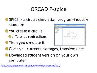
ORCAD/Cadence • Computer-Aided Engineering (CAE) tools cover allaspectsofengineering design from drawings to analysis to manufacturing. • Computer-aided design (CAD) is a category of CAE that is related to the physical layout and drawing development of a system design. • Electronic design automation (EDA) reduce development time and cost because they allow designs to be simulated and analyzed prior to purchasing and manufacturing hardware. • Capture contains extensive parts libraries that may be used to generate schematics that stand alone or that interact with PSpice, or Layout, or both simultaneously. • The pins on a Capture part can be mapped into the pins of a PSpice model and/or the pins of a physical package in Layout. • PSpice is a CAE tool that contains the mathematical models for performing simulations, and Layout is a CAD tool that converts a symbolic schematic diagram into a physical representation of the design. • Netlists are used to interconnect parts within a design and connect each of the parts with its model and footprint. • In addition to being a CAD tool, Layout also functions as a front-end CAM tool by generating the data on which other CAM.
PCB • Printed Circuit Board (PCB) • A PCB consists of two basic parts: • a substrate (the board) • printed wires (the copper traces). • The substrate provides a structure that physically holds the circuit components and printed wires in place and provides electrical insulation between conductive parts. • A common type of substrate is FR4, which is a fiberglass–epoxy laminate. Substrates are also made from Tefl on, ceramics, and special polymers. • During manufacturing the PCB starts out as a copper clad substrate as shown in Fig. 1-2. A • rigid substrate is a C-stage laminate (fully cured epoxy). The copper cladding may be copper • that is plated onto the substrate or copper foil that is glued to the substrate. • A substrate can have copper on one or both sides. Multilayer boards are made up of one or more single- or double-sided substrates called cores. A core is a copper-plated epoxy laminate. The cores are glued together with one or more sheets of a partially cured epoxy.
PCB Design Process: OrCAD Layout • Layout is used to design the PCB by generating a digital description of the board layers for photoplotters and CNC machines, which are used to manufacture the boards. • There are separate layers for : • routing copper traces on the top, bottom, and all inner layers; • drill hole sizes and locations; • soldermasks; • silk screens; • solder paste; • part placement; • board dimensions.
OrCAD Layout: File format • Layout format files (.MAX) • Layout uses .MAX extension while you are designing your board. • Gerber Files • When you are ready to fabricate your board, Layout postprocesses the design and converts it into a format that the photoplotters and CNC machines can use (Gerber files). • A separate Gerber file is created for each of the layers (distinguible by the extension). • Assembly layers • These files are used for automated assembly of a finished board. • Solder-paste layer. It is used to make a contact mask for selectively applying solder paste onto the PCB’s pads so that components can be reflow soldered to the board. There may be a solder-paste layer for the top side of the board (.SPT) and one for the bottom side (.SPB). • Assembly layer, which contains information for automatic component placement machines (pick-and-place machines) as to the part type, its position, and its orientation on the board. As with the soldermask, there may be an assembly layer for the top side of the board (.AST) and one for the bottom side (.ASB).
Overview of the Design Flow • Basic procedure for generating a schematic in Capture and converting the schematic to a board design in Layout: • Start Capture and set up a PCB project using the PC Board wizard. • Make a circuit schematic using OrCAD Capture. • Use Capture to generate a Layout netlist and save it as a .MNL file for Layout. • Start Layout and select a PCB technology template (.TCH file). • Save the Layout project as a .MAX project file. • Use Layout to import the .MNL netlist into the .MAX file. • Make a board outline. • Position the parts within the board outline. • Autoroute the board. • Run the postprocessor to generate fi les used to manufacture the PCB.
Industry Standards • How big and what shape should the board outline be? • Where should the parts be placed and in what order? • What kind of layer stackup should be used? • How wide and far apart should the traces be routed? • What grounding and shielding techniques should be used? • Is there a “right” way to do it, and who says so? • There are several standards related to PCB design to solve these questions. • The organizations below set standards that may be guides, rules for certification, or even laws: • Institute for Printed Circuits (IPC-Association Connecting Electronics Industries) • Electronic IndustriesAlliance (EIA) • Joint Electron Device Engineering Council (JEDEC) • International Engineering Consortium (IEC) • Military Standards • American National Standards Institute (ANSI) • Institute of Electrical and Electronics Engineers (IEEE)
PCB Issues Performance classes PCBs can fall into any of three end-use performance classes. ● Class 1, General Electronic Products, includes general consumer products (televisions, electronic games, and personal computers) that are not expected to have extended service lives and are not likely to be subjected to extensive test or repairabilityrequirements. ● Class 2, Dedicated-Service Electronic Products, includes commercial and military products that have specifi c functions such as communications, instrumentation, and sensor systems, from which high performance is expected over a longer period of time. Since these items usually have a higher cost they are usually repairable and must meet strictertestingrequirements. ● Class 3, High-Reliability Electronic Products, includes commercial and military equipment that has to be highly reliable under a wide range of environmental conditions. Examples include critical medical equipment and weapons systems. They typically have more stringent test specifications and possess greater environmental robustness and reworkability. Producibilitylevels The three producibility levels are: ● Level A, general design—preferred complexity ● Level B, moderate design—standard complexity ● Level C, high design—reduced producibility complexity
Ground Issues Typicalsignal and return connection schemes. Left) parallelconnected Right) Seriesconnected Signal and return connection parallel and seriesschemes in Layout
Common ground plane • Solve routing problems • If the signal path is relatively close to the return path, the return signal will automatically flow through the GND plane directly below the signal trace (in DC circuits, current follows the path of least resistance). • AC currents will follow the path of least impedance and, particularly on PCBs, the path of least inductance • In a typical PCB the power distribution system contains one or more power and ground planes. • The power and ground planes are like very wide traces (have little inductance) and are usually adjacent to each other (high capacitance). • Ok for the power distribution system • Problem occurs in high-speed digital systems when gates switch from one state to another: switchingnoise.
Switching Noise the supply voltages across the PCB while the gate is switching Because the power and ground planes are not superconductors there is a drop in voltage between the supply pins of the gate and where power is connected to the PCB (same for the return plane). Remember that there is always some amount of resistance and inductance even on the so-called ground plane. Rail collapse: the drop in the positive rail Ground bounce: the rise in ground potential. The primary purpose of bypass capacitors in digital circuits is to promote a stable PCB power distribution system and prevent rail collapse and ground bounce. The bypass capacitors act as lowpassfiters and short out power supply transients (noise) before they get to the amplifliers.
Split power and ground planes The solution to the problem of digital noise being injected into analog circuitry through the supply planes is to segregate the analog components from the digital ones and eliminate common return paths. Segregating the components is straightforward; the components are physically placed in different places on the board. Continuous plane Split plane Moated plane Isolated, coutinuous plane