Download
1 / 39
390 likes | 655 Views
Machine Structures Lecture 17 – Introduction to CPU Design.

E N D
Machine StructuresLecture 17 – Introduction to CPU Design Fedora Core 6 (FC6) just out The latest version of the distrohas been released; they suggest using Bittorent to get it. Performance improvements and support for Intel-based Macs. (Oh, Apple just upgraded Pros’ CPU to Intel Core 2 Duo). fedoraproject.org
Five Components of a Computer Keyboard, Mouse Computer Devices Memory (passive) (where programs, data live when running) Processor Disk(where programs, data live when not running) Input Control Output Datapath Display, Printer
The CPU • Processor (CPU): 计算机的核心,完成所有的工作 (操作数据及决策) • Datapath(数据通道): processor的一部分,功能是执行运算 (肌肉部分brawn) • Control: processor的一部分,指挥(控制)datapath做什么 (大脑部分brain)
Stages of the Datapath : Overview • 问题: 将 “执行整个指令”的块做为一个整体 • 太大(该块要执行从取指令开始的所有操作) • 效率不高 • 解决方案: 将 “执行整个指令” 的操作分解为多个阶段(stage),然后将所有阶段连接在一起产生整个datapath • 每一阶段更小,从而更容易设计 • 方便优化其中一个阶段,而不必涉及其他阶段
Stages of the Datapath (1/5) • MIPS有多种指令: 共同的步骤是些什么? • Stage 1: 取指 • 无论何种指令, 首先必须把32-位指令字从内存中取出。(可能涉及缓存结构) • 在这一步,我们还需要增加PC (即PC = PC + 4, 以指向下一条指令,由于是按字节寻址,故+4)
Stages of the Datapath (2/5) • Stage 2: 指令译码Instruction Decode • 在取到指令后, 下一步从各域(fields)中得到数据(对必要的指令数据进行解码) • 首先,读出Opcode,以决定指令类型及字段长度 • 接下来,从相关部分读出数据 • for add, read two registers • for addi, read one register • for jal, no reads necessary
Stages of the Datapath (3/5) • Stage 3: ALU (Arithmetic-Logic Unit) • 大多数指令的实际工作在此部完成: 算术指令 (+, -, *, /), shifting, logic (&, |), comparisons (slt) • what about loads and stores? • lw $t0, 40($t1) • 要访问的内存地址 = $t1的值+ 40 • so we do this addition in this stage
Stages of the Datapath (4/5) • Stage 4:内存访问Memory Access • 事实上只有load和store指令在此stage会做事; 其它指令在此阶段空闲idle或者直接跳过本阶段 • 由于load和store需要此步,因此需要一个专门的阶段 stage来处理他们 • 由于cache系统的作用,该阶段有望加速 • 如果没有caches,本阶段stage会很慢
Stages of the Datapath (5/5) • Stage 5: 写寄存器Register Write • 大多数指令会将计算结果写到寄存器 • 例如: arithmetic, logical, shifts, loads, slt • what about stores, branches, jumps? • don’t write anything into a register at the end • these remain idle during this fifth stage or skip it all together
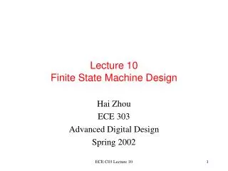
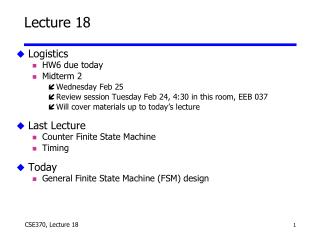
ALU 2. Decode/ Register Read 5. Reg. Write 1. Instruction Fetch 4. Memory 3. Execute Generic Steps of Datapath rd instruction memory registers PC rs Data memory rt +4 imm
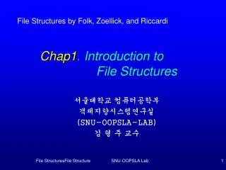
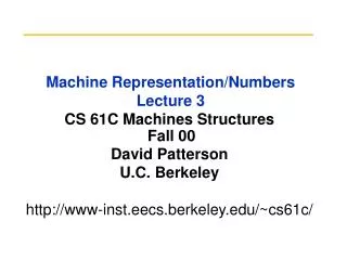
Datapath Walkthroughs (1/3) • add $r3,$r1,$r2 # r3 = r1+r2 • Stage 1: 取指, 增加PC • Stage 2: 解码,知道是add指令, 读寄存器$r1和 $r2 • Stage 3: 将上一步获得的两个值相加 • Stage 4: idle (不必读写内存) • Stage 5: 将第三步Stage 3的结果写入寄存器 $r3
reg[1] 3 reg[1]+reg[2] 1 reg[2] 2 ALU add r3, r1, r2 Example: add Instruction instruction memory registers PC Data memory imm +4
Datapath Walkthroughs (2/3) • slti $r3,$r1,17 • Stage 1: 取指, 增加PC • Stage 2: 解码,知道是slti, 然后读寄存器$r1 • Stage 3: 比较上一步获得的值和17 • Stage 4: idle • Stage 5: 将第三步的结果写入寄存器$r3
reg[1] x reg[1]<17? 1 3 ALU 17 slti r3, r1, 17 Example: slti Instruction instruction memory registers PC Data memory imm +4
Datapath Walkthroughs (3/3) • sw $r3, 17($r1) • Stage 1: 取指, 增加PC • Stage 2: 解码,知道是sw, 然后读寄存器$r1 和$r3 • Stage 3: 将17与寄存器 $r1的值相加 (上一步获得) • Stage 4: 将寄存器$r3的值(第2步取得)写到第3步计算得到的内存地址 • Stage 5: idle (不必写入寄存器)
reg[1] x reg[1]+17 1 reg[3] 3 ALU 17 MEM[r1+17]<=r3 SW r3, 17(r1) Example: sw Instruction instruction memory registers PC Data memory imm +4
Why Five Stages? (1/2) • 是否能有不同的步骤? • 是, 其他结构是这样的 • 为什么MIPS有5步,如果指令至少在某一步空闲(idle)? • 5步可以将所有的操作统一. • There is one instruction that uses all five stages: the load
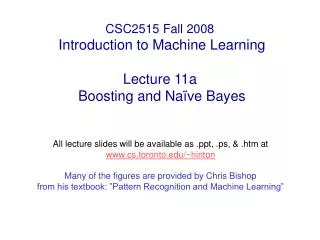
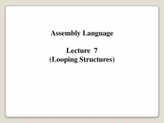
Why Five Stages? (2/2) • lw $r3, 17($r1) • Stage 1: 取指, 增加PC • Stage 2: 解码,知道是lw, 读寄存器$r1 • Stage 3: 将17与寄存器 $r1的值相加(上一步得到) • Stage 4: 从上一步计算得到的内在地址中读值 • Stage 5: 将上一步得到的值写入寄存器$r3
reg[1] x reg[1]+17 1 3 ALU MEM[r1+17] 17 LW r3, 17(r1) Example: lw Instruction instruction memory registers PC Data memory imm +4
rd instruction memory PC registers rs Data memory ALU rt +4 imm opcode, funct Controller Datapath Summary • 为了执行指令,需要有基于数据变换的数据通道(Datapath) • 控制器controller 产生正确的变换
What Hardware Is Needed? (1/2) • PC寄存器:用于踊跃记录下一个指令的内存地址 • 通用寄存器 • 用于第二步 (Read) 和第五步(Write) • MIPS has 32 of these • 内存 • 用于第一步 (Fetch) 和第 4 步(R/W) • Cache系统使得这两步和其他步骤同样快(平均而言)
What Hardware Is Needed? (2/2) • ALU • 用于第三步 • 用于执行所有必要的函数功能: arithmetic, logicals, etc. • 后面会进行详细设计 • 其他寄存器 • 为了实现每个时钟周期执行一步, 在各步(stage)之间插入寄存器以保存阶段变换过程中的中间数据和控制信号. • 注: 寄存器是通用名词,意即保存位的实体. 不是所有寄存器都在“寄存器文件”中.
2. Decode/ Register Read 5. Reg. Write 1. Instruction Fetch 4. Memory 3. Execute CPU clocking (1/2) 对每个指令, 如何控制数据通道中信息的流动? • 单周期CPU: 指令的所有阶段在一个长的时钟周期中完成. • The clock cycle is made sufficient long to allow each instruction to complete all stages without interruption and within one cycle.
2. Decode/ Register Read 1. Instruction Fetch 5. Reg. Write 4. Memory 3. Execute CPU clocking (2/2) 对每个指令, 如何控制数据通道中信息的流动? • 多时钟周期CPU: 每个时钟周期,执行一个stage指令. • 时钟和最慢的stage一样长. 和单时钟执行相比,有几个好处: 某个指令未用的阶段stages可以跳过,指令可以进入流水线pipelined (重叠).
Verilog big idea: Time in code • One difference from a prog. lang. is that time is part of the language • part of what trying to describe is when things occur, or how long things will take • In both structural and behavioral Verilog, determine time with #n : event will take place in n time units • structural: not #2(notX, X) says notX does not change until time advances 2 ns • assign #2 Z = A ^ B; says Z does not change until time advances 2 ns • Default unit is nanoseconds; can change
2-input Mux with delay module mux2 (in0, in1, select, out); input in0,in1,select; output out; wire s0,w0,w1; not #1 (s0, select); // 1ns gate delays and #1 (w0, s0, in0), (w1, select, in1); or #1 (out, w0, w1); endmodule // mux2
Testing in Verilog • Code examples so far define hardware modules. • Need separate code to test the module (just like C/Java) • Since hardware is hard to build, major emphasis on testing in HDL • Testing modules called “test benches” in Verilog; • like a bench in a lab dedicated to testing • Could design special hardware blocks to test other blocks - awkward! Use behavioral Verilog
Testing Verilog • Create a test module for mux2: module testmux; reg a, b, s; reg expected; wire f; mux2 myMux(.select(s), .in0(a), .in1(b), .out(f)); /* add testing code */ endmodule • Outline: declare variable to use for connection from testbench, instantiate module, specify stimulus, (compare output to expected), print results (or view with waveform viewer)
Testing continued Now we write code to try different inputs by assigning to connections: … initial begin #0 s=0; a=0; b=1; expected=0; #10 a=1; b=0; expected=1; #10 s=1; a=0; b=1; expected=1; #10 $stop; end
Testing continued • Use $monitor to watch some signals and see every time they are updated: … initial $monitor( "select=%b in0=%b in1=%b out=%b expected out=%b time=%d", s, a, b, f, expected, $time); • $time is system function which gives current (simulated) time
Output select=0 in0=0 in1=1 out=x, expected out=0 time= 0 select=0 in0=0 in1=1 out=0, expected out=0 time= 2 select=0 in0=1 in1=0 out=0, expected out=1 time= 10 select=0 in0=1 in1=0 out=1, expected out=1 time= 12 select=1 in0=0 in1=0 out=1, expected out=0 time= 20 select=1 in0=0 in1=0 out=0, expected out=0 time= 22 • Expected value (of behavioral Verilog) matches actual value (of structural Verilog), so module works for the inputs patterns tested. • Simple to extend this testbench to do exhaustive testing.
For more help ... • Read Verilog Tutorial for many more ideas on building tests benches, including: • more verilog behavioral constructs • more looping constructs • use verilog to generate expected output (rather than enumerate by mimicking behavior of HW module) • more output routines • testing circuits with state • Read ModelSim manual for use of waveform viewer
Specifying a clock signal ... initial begin CLK = 1'b0; forever #1 CLK = ~CLK; end ... • No built in clock in Verilog, so specify one • Clock CLK above alternates forever in 2 ns period: 1 ns at 0, 1 ns at 1
Accumulator Example //Accumulator module acc (CLK,RST,IN,OUT); input CLK,RST; input [3:0] IN; output [3:0] OUT; wire [3:0] W0; add4 myAdd (.S(W0), .A(IN), .B(OUT)); reg4 myReg (.CLK(CLK), .Q(OUT), .D (W0), .RST(RST)); endmodule // acc • This module uses prior modules, using wire to connect output of adder to input of register
Accumulator TestBench module accTest; reg [3:0] IN; reg CLK, RST; wire [3:0] OUT; acc myAcc (.CLK(CLK), .RST(RST), .IN(IN), .OUT(OUT)); initial begin CLK = 1'b0; repeat (20) #5 CLK = ~CLK; end ... • Clock has a oscillation cycle of _ ns?
Part II ... initial begin #0 RST=1'b1; IN=4'b0001; #10 RST=1'b0; end initial $monitor("time=%0d: OUT=%1h", $time,OUT); endmodule // accTest • What does this initial block do? • What is output sequence? • How many lines of output?