Download
1 / 56
600 likes | 707 Views
Exploring the importance of head position in aviation, focusing on the Opto-kinetic Cervical Reflex to prevent spatial disorientation accidents and control reversal errors. Research studies and findings are discussed in relation to pilot safety.

E N D
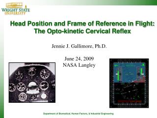
Head Position and Frame of Reference in Flight: The Opto-kinetic Cervical Reflex Jennie J. Gallimore, Ph.D. June 24, 2009 NASA Langley
Topics • Spatial Disorientation • Attitude Indicator • OKCR Research • Considerations for Cockpit Displays • Other On Going Research at WSU
Spatial Disorientation • The inability of the flight crew to correctly perceive attitude, altitude, or airspeed of the aircraft in relationship to the earth and other points of reference. • SD has been categorized into three types. • Type I unrecognized (where most mishaps are classified) • Type II recognized • Type III incapacitating
Spatial Disorientation Accidents • US Air Force 1991-2000, 20.2% of accidents, 60 lives, 1.4 billion dollars [Davenport00]. • US Army reported 27% [Kuipers90]. • US Navy and Marine Corp, 26%, 101 accidents [Johnson00] • Three times as many lives were lost for SD related mishaps compared to non-SD related mishaps. • Mishap data also indicate that pilots who experience SD are very experienced, and the mishap rate has not decreased in the last 20 years.
First Flight Instrument? Wright 1909 Military FlyerSlip Ribbon (first flight instrument)
First Mechanical Flight Instrument • Sperry’s bank and turn indicator, 1918 • Worked best in clear weather
First “Blind” Sortie • Sep 24th 1929 under direction of Guggenheim in NY (Mitchel Field) • First ‘Blind’ sortie, takeoff to landing • First use of artificial horizon, Kollsman altimeter, and directional gyro
Attitude Indicator Level flight 20-degree turn
Attitude Indicator Example • Real World • Plane moves • Horizon remains static • Indicated World • Plane remains static • Horizon moves • Indicator reverses reality • Dangerous if visual reference • is lost • Pilot disorientation • Control reversal errors
Opto-Kinetic Cervical Reflex (OKCR) • Pilots align their heads toward the horizon during Visual Meteorological Conditions (VMC) flight. • Pilots do not tilt their heads during Instrument Meteorological Conditions (IMC) flight. • Visual to Instrument transition can cause reversal errors.
Head Tilt • Patterson (1989) noticed that pilots align their heads with the horizon. • If they are aligning their heads with the aircraft then the view from the windscreen is a fixed horizon (not moving).
Opto-Kinetic Cervical Reflex (In-flight) Horizon Line with 73 degrees of bank angle F/A-18 aircraft (Blue Angel) 73 degrees of bank (VMC, +Gz Turn). OKCR Head tilt = 31degrees away from the Gz axis.
WSU Research Investigating Head Tilt • Patterson (1995, 1997) • Smith et al (1997) • Merryman et al (1997) • Gallimore et al (1999, 2000) • Liggett & Gallimore (2001) • Gallimore, Liggett & Patterson (2001) • Others since
Horizon Roll Vs. Head Roll for Low-Level Route Patterson et al.
Results:Head tilt with respect to aircraft bank during low-level routeGallimore, et al (1999)
Reversal Error • Tendency for pilots to mistake motion of the artificial horizon as a relative motion of the wings. • Pilots roll or pitch the aircraft in opposite direction. • Researchers who have documented this error • Fitts and Jones (1947) • Johnson and Roscoe (1972) • Roscoe and Williges (1975) • Roscoe (1986) - Boeing 747 accident
Sensory-Spatial Conflict and Control Reversal Error (Patterson et al findings) Control reversal error during IMC “out” to “in” visual transition. • Experienced U.S. military rated pilots commit 25-65% reversal errors. • Likelihood of reversal errors by general aviation pilots is probably even greater. • A reversal error can lead to flight into terrain or a graveyard spiral. • This is likely what happened to the pilot of Air India and to John F. Kennedy, Jr. References on reversal errors: Patterson, et al, 1997 Braithwaite,et al, 1998 Gallimore, et al., (1999) Liggett & Gallimore (in press)
Number and Magnitude of Reversal ErrorsGallimore, et al findings 40 Degrees 60 Degrees 100 Degrees 9 errors out of 24 8 errors out of 24 6 errors out of 24 1(.04%) 5(20.83%) 4(17.39%) VMC 5(20.83%) 4(17.39%) 4(17.39%) IMC Average reversal error magnitude 9.34 o Combined Average reversal error magnitude 28.96 o Average reversal error magnitude 9.30 o
Transitions What happens during the transition from visual to instruments? • The pilot’s view of the cockpit suddenly becomes stationary as his view of the display’s artificial horizon begins moving. • Pilots must instantly reverse their orientation strategy. • Pilots sensory-spatial compatibility between the control stick motion and visual feed back.
Summary • Pilots reflexively tilt heads toward horizon during VMC roll maneuvers. • Head movement acts to stabilize retinal image. • Generated by motion on retina, not vestibular. • Stabilized horizon is the primary visual cue. • Peripherally viewed cockpit structures secondary cues. • Secondary cues move with airframe. • Control movement compatible with secondary cues.
Summary (Cont.) • Beyond 40 degrees of aircraft roll there is a decrease in head displacement, so pilots can not stabilize the horizon. • Horizon acceleration, stabilization of secondary cues. • Sudden switch may lead to false perceptions. • When transitioning from visual to instruments • motion reversal b/w outside and inside visual cues • control display incompatibility • need to switch cognitive model
How does OKCR affect current display technologies? • Head down Attitude Indicator • Reversal errors • HUD • Head may tilt out of the HUD eye box and pilot may not see a pull up X.
HUD • The Head Up Display (HUD) presents symbols to the pilot, displaying them over the real world.
How does OKCR affect current display technologies? (cont) • NVG • HUD symbology on the NVG. Head movements are not tracked. As pilot changes head position, display horizon line is no longer conformal to the real horizon. • Pilots see HUD information designed for fixed on-axis aircraft viewing regardless of head position. Pilots may not realize they are not flying in the direction they are looking.
Research Issues • What frames of reference are important for a pilot to maintain orientation? • World - world is fixed and everything moves within it. • Aircraft - aircraft is fixed and everything moves around it. • Pilot - pilot is fixed and everything moves in relation to him.
Research Issues • What symbology is appropriate for HMDs? • HUD symbology is being considered for use on HMDs. • HUD symbology is being used on NVGs. • How do sensory reflexes affect perceived frame of reference? • OKCR, under VMC pilots align their head with the horizon.
Research Issues • How do visual frames of reference interact with vestibular and proprioceptive inputs to provide the pilot with an "awareness" of their orientation? • What contributing cognitive factors affect spatial orientation? • How will HMD attitude symbology affect frames of reference in VMC and IMC? • How will transitions be impacted? • How can we detect when a pilot is spatially disoriented?
Research Issues for HMD Symbology Design • What spatial sensory reflexes and visual illusions influence pilot’s perception of frame of reference? • Will cognitive capture affect pilots perceptions of frame of reference? Will cognitive capture result in more transitions between symbology and the real world? • When pilots transition between a perceived stationary horizon (real world cues) to a moving symbol horizon on the HMD, do they perceive the horizon symbol as stationary? • What type of symbology will help provide the perception of a stationary horizon?
Research Issues for HMD Symbology Design • If HMD symbology is used for attitude information as well as targeting, how will switching between these tasks affect frame of reference? • Will pilots have a greater risk of spatial disorientation if they look off-axis more often? • How will secondary flight cues be affected by use of HMDs? • What current or new measures should be employed to determine if a pilot is spatially disoriented?
HMD Research and the OKCR Experiment I • Test adequacy of Mil-Std HUD symbology presented on a see-through HMD during various tasks. • VMC flight task • Pilots were instructed to bank at specific angles, rather than to bank around a waypoint. • 12 Subjects • HMD Kaiser Pro – Binocular HMD, 40o circular FOV, 100% overlap, 1280 x 1024 resolution.
HMD Research and the OKCR Experiment II • Investigate visual cues in an immersed HMD simulation system using HUD symbology. • VMC Flight task • Varied resolution (640 x 480 & 800 x 600), HUD symbol size (small and large) • Pilots instructed to follow a yellow track line over Pensacola, FL • 6 subjects • Virtual Research V8 HMD system, 48o H x 32o V, 100% overlap
HMD Research and the OKCR Experiment III • Investigate the effects of non-congruent motion on performance in an immersive HMD system. • VMC flight task flown on land and on Navy mind sweeper in Pensacola Bay. • Pilots instructed to follow a yellow track line over Pensacola, FL • 9 subjects • Sony i-glasses , 24o H x 18o V, 100% overlap, 789 x 230 Resolution
OKCR Differences • Different visual scenes/cues cause difference in pilot OKCR response • Reducing FOV • Manipulating altitude • Amount of head tilt depends on amount of retinal movement. • Reduction in peripheral vision may play a role • Reducing FOV may reduce how compelling the visual horizon appears
OKCR Differences • Immersive HMD simulation studies did not provide any secondary visual cues (cockpit structures). • Do pilots reduce head movements when they lack a stabilizing cue? • If experiencing simulator sickness may reduce head movements.
Control Reversal Errors HMDLiggett and Gallimore findings • Overall CRE rate 28%, similar to previous studies. • Magnitude range: 6 degrees to 201 degrees • A conformal horizon symbol did not reduce CREs. • Because we know they were not tilting in IMC, they still had to change frames of reference from world to aircraft.
Control Reversal Errors HMDLiggett and Gallimore findings • Dependent measure: Altitude Change • Significant difference • CRE group average: 3382 ft MSL • No CRE group average: 1810 ft MSL • Pilots with CREs obviously confused. • Focusing on pitch and bank information in central part of symbology. • Fail to scan airspeed and altitude information.
1. Recognition of pilot spatial awareness strategies 3. Avoidance and recognition of Visual Illusions (perspective illusion) 2. Avoidance and recognition of spatial disorientation (VMC-IMC form/ reversal error) 4. Design of flightdeck displays