Understanding Pipelining in Modern CPU Architectures: Concepts and Hazards
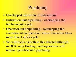
Pipelining is a crucial technique in CPU design that enhances instruction throughput by overlapping the execution of multiple instructions. This implementation technique divides instruction processing into stages, enabling a more efficient use of functional units and improved performance. However, it introduces challenges such as structural, control, and data hazards that can cause stalls in the pipeline. This overview explores the mechanics of pipelining, its benefits, the common hazards faced, and solutions like forwarding and instruction reordering that optimize the execution flow.

Understanding Pipelining in Modern CPU Architectures: Concepts and Hazards
E N D
Presentation Transcript
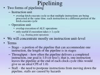
Pipelining: Definition • An implementation technique • instructions are overlapped in execution. • A key technique for improving performance in many, if not all, contemporary processors. • In multiple cycle implementation, • steps of instructions are executed in different stages. • functional units for different purposes • In pipelined datapath • Some units used more efficiently • Some units must be replicated
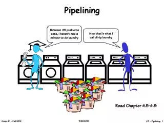
Laundry Analogy • Four different stages • Identical time (30 min)
Pipelined Datapath • MIPS instructions classically take five steps: • IF - Fetch instruction from memory • ID - Read registers while decoding the instruction • EX - Execute the operation or calculate an address • MEM - Access an operand in memory • WB - Write result into a register
IF ID EX MEM WB IF ID EX MEM WB IF Program execution order 200 400 600 1200 800 1800 1000 1400 1600 Time ID ID ID IF EX MEM WB lw $t1, 100($s1) IF EX MEM WB lw $t2, 200($s1) MEM IF EX WB lw $t2, 300($s1) Pipelined vs. Nonpipelined 200 400 600 1200 800 1800 1000 1400 Program execution order 1600 Time lw $t1, 100($s1) lw $t2, 200($s1) lw $t2, 300($s1)
Aspects of Pipelining • Latency is the same (usually a little worse) • Instruction throughput increases. • What is the ideal speedup due to pipelining? • In practice, it is hard to achieve the theoretical speedup because of 1) imperfectly balanced instructionsteps and 2) hazards. • Features of MIPS that make the pipelining easy: • Instructions are of the same length. • Few instruction formats • Load/store architecture • Operands are aligned in memory
Pipelining Problems • Structural hazards: • Hardware cannot support the combination of instructions in the same clock cycle. • one memory for instruction and data. • Control hazards: • branch instructions change the flow of instructions • Data hazards: • an instruction depends on the result of a previous instruction • The result may not be available when needed by the current instruction
IF EX MEM WB ID ID ID Pipeline Stalls on Control Hazards Program execution order 200 400 600 1200 800 1800 1000 1400 1600 • Assume that we can resolve branch in the second step • Next instruction cannot start until the end of second cycle. • The pipeline stops issuing new instruction, or it stalls. IF EX MEM WB add $t1, $s1, $s2 IF EX MEM WB beq $t2, $t3, 40 200ps lw $t4, 300($s1) 400ps
IF EX MEM WB ID ID ID Predict the Outcome Program execution order 2 4 6 12 8 18 10 14 16 • One simple approach is to predict that branches will always fail. IF EX MEM WB add $t1, $s1, $s2 IF EX MEM WB beq $t2, $t3, 40 2 ns lw $t4, 300($s1) 2 ns • When otherwise occurs (branch is indeed taken), then started instruction is discarded (flushed out) and the instruction at the branch address will start executing.
ID ID ID IF EX MEM WB add $t1, $s1, $s2 2 ns IF EX MEM WB 2 ns Delayed Branches • A solution actually used by the MIPS architecture. • Delayed branches always execute next sequential instruction • MIPS software places an instruction immediately after the delayed branch instruction that is not affected by the branch • Compilers fill about 50% of the branch delay slots with useful instructions Program execution order 2 4 6 12 8 18 10 14 16 IF EX MEM WB beq $t2, $t3, 40 lw $t4, 300($s1)
Data Hazards • An instruction depends on the results of a previous instruction still in the pipeline. • Example:add $s0, $t0,$t1sub $t2, $s0, $t3 • This is also known as data dependency. • Normally, these types of data hazards could severely stall the pipeline • We have to add three bubbles in the pipeline.
Forwarding • First solution: compiler optimizations rearrange the instruction sequence. • Second solution: forwarding (or bypassing). • ALU creates the result much sooner than the result is actually written back to a register. • As soon as the ALU creates it, the result immediately can be forwarded to the next instruction. • Direct use of ALU results.
Direct use of ALU result Forwarding
Forwarding: Examples • Forwarding when an R-format instruction following a load instruction.
Reordered code. No data hazard. lw $t0, 0($t1) lw $t2, 4($t1) addi $s1, $t0, 0xA addi $s0, $t2, 0x5 Reordering Code to Avoid Pipeline Stalls lw $t0, 0($t1) lw $t2, 4($t1) addi $s0, $t2, 0x5 addi $s1, $t0, 0xA Code that causes a pipeline stall due to data hazard.
Instruction and Data Flow • Instruction and data move generally from left to right with two exceptions: • Write-back stage, which places the result back into the register file in the middle of the data path => data hazard • The selection of the next value of the PC, choosing between the incremented PC and the branch address from the MEM stage => control hazard
Design of Pipelined Datapath • Break the datapath into smaller segments • These segments can be shared by instructions • Use registers between two consecutive segments of the datapath to hold the intermediate results. • Pipeline registers
rt rt rt Example: IF of lw M U X EX/MEM MEM/WB IF/ID ID/EX Add 4 Add Shift Left 2 PC M U X Instruction Memory DataMemory ALU Registers M U X 32 16 SignExt
Example: ID of lw M U X EX/MEM MEM/WB IF/ID ID/EX Add 4 Add Shift Left 2 PC M U X Instruction Memory DataMemory ALU Registers M U X 32 16 SignExt rt rt rt
Example: EX of lw M U X EX/MEM MEM/WB IF/ID ID/EX Add 4 Add Shift Left 2 PC M U X Instruction Memory DataMemory ALU Registers M U X 32 16 SignExt rt rt rt
Example: MEM of lw M U X EX/MEM MEM/WB IF/ID ID/EX Add 4 Add Shift Left 2 PC M U X Instruction Memory DataMemory ALU Registers M U X 32 16 SignExt rt rt rt
Example: WB of lw M U X EX/MEM MEM/WB IF/ID ID/EX Add 4 Add Shift Left 2 PC M U X Instruction Memory DataMemory ALU Registers M U X 32 16 SignExt rt rt rt
Example 2: sw, EX stage M U X EX/MEM MEM/WB IF/ID ID/EX Add 4 Add Shift Left 2 PC M U X Instruction Memory DataMemory ALU Registers M U X 32 16 SignExt
Example 2: MEM of sw M U X EX/MEM MEM/WB IF/ID ID/EX Add 4 Add Shift Left 2 PC M U X Instruction Memory DataMemory ALU Registers M U X 32 16 SignExt
Example 2: WB of sw M U X Oops! Nothing happening EX/MEM MEM/WB IF/ID ID/EX Add 4 Add Shift Left 2 PC M U X Instruction Memory DataMemory ALU Registers M U X 32 16 SignExt
Summary So Far • Not all instructions require the complete datapath. • No information transfer from one pipeline stage to the next is possible except through pipeline registers • Each component can be used only in a single pipeline stage • Everything that happened in the previous stage will be overwritten.
Pipelined Control • PC is written on each clock cycle (no write signal) • No write signals for pipeline registers. • IF stage: no control signal since instruction is read and PC is updated each cycle • ID stage:No control signals • EX stage:RegDst, ALUOp, ALUSrc • MEM stage:branch, MemRead, MemWrite • WB stage:MemtoReg, RegWrite
Add ALU Pipelined Datapath with Control Signals M U X PCSrc MEM/WB ID/EX EX/MEM IF/ID Add Shift Left 2 4 branch RegWrite MemtoReg MemWrite ALUSrc zero PC Registers M U X M U X Instruction Memory DataMemory ALUcntrl SignExt 16 32 [15 0] 6 [20 16] rt M U X [15 11] rd MemRead ALUOp RegDst
Control Signals for Instructions • Nine control signals that start in the EX stage • Main control unit generates the control signals during the ID stage.
Control WB MEM instruction WB EX MEM WB IF/ID ID/EX EX/MEM MEM/WB Control Lines for the Last Three Stages
Add ALU Pipelined Datapath with Control Signals PCSrc M U X ID/EX EX/MEM Control WB M WB MEM/WB EX M IF/ID WB Add Shift Left 2 4 RegWrite branch MemtoReg MemWrite ALUSrc zero PC Registers M U X M U X Instruction Memory DataMemory ALUcntrl SignExt 16 32 [15 0] [20 16] MemRead M U X [15 11] ALUOp RegDst
Example • Show how these five instructions will go through the pipeline:lw $10, 20($1)sub $11, $2, $3and $12, $4, $5or $13, $6, $7add $14, $8, $9
Add ALU Clock 1 ID: before<1> EX: before<2> MEM: before<3> WB: … IF: lw $10, 20($1) PCSrc M U X ID/EX EX/MEM 00 Control 00 WB 000 00 000 M WB MEM/WB 0 0 0 0000 00 EX M IF/ID 0 WB 0 0 0 Add Shift Left 2 4 RegWrite branch MemtoReg MemWrite ALUSrc zero PC Registers M U X M U X Instruction Memory DataMemory ALUcntrl SignExt 32 16 [15 0] [20 16] M U X [15 11] MemRead ALUOp RegDst
Add ALU Clock 2 ID: lw $10, 20($1) EX: before<1> MEM: before<2> WB: … IF: sub $11, $2, $3 PCSrc M U X ID/EX EX/MEM 00 11 Control WB 00 010 000 M WB MEM/WB 0 0 0001 0 00 EX M IF/ID WB 0 0 0 0 Add Shift Left 2 4 RegWrite branch MemtoReg MemWrite ALUSrc zero PC Registers M U X M U X Instruction Memory DataMemory ALUcntrl SignExt 32 16 [15 0] [20 16] M U X [15 11] MemRead ALUOp RegDst
Add Clock 3 ID: sub $11, $2, $3 EX: lw $10, 20($1) MEM: before<1> WB: … IF:and $12, $4, $5 PCSrc M U X ID/EX EX/MEM 11 10 Control WB 000 00 010 M WB MEM/WB 0 0 0 1100 0 00 EX M IF/ID WB 0 0 1 Add Shift Left 2 4 RegWrite branch MemtoReg MemWrite ALUSrc zero PC ALU Registers M U X M U X Instruction Memory DataMemory ALUcntrl SignExt 32 16 [15 0] [20 16] M U X [15 11] MemRead ALUOp RegDst
Add Clock 4 ID:and $12, $4, $5 EX: sub $11, $2, $3 MEM: lw $10, 20($1) WB: … IF:or $13, $6,$7 PCSrc M U X ID/EX EX/MEM 10 10 Control WB 11 000 000 M WB MEM/WB 1 1 0 1100 10 EX M IF/ID WB 0 0 0 0 Add Shift Left 2 4 RegWrite branch MemtoReg MemWrite ALUSrc zero PC ALU Registers M U X M U X Instruction Memory DataMemory ALUcntrl SignExt 32 16 [15 0] [20 16] M U X [15 11] MemRead ALUOp RegDst
Add Clock 5 ID:or $13, $6,$7 EX:and $12, $4, $5 MEM:sub … WB: lw IF:add $14, $8, $9 PCSrc M U X ID/EX EX/MEM 10 10 Control WB 10 000 000 M WB MEM/WB 1 0 1 1100 EX M IF/ID 10 WB 1 0 0 0 Add Shift Left 2 4 RegWrite branch MemtoReg MemWrite ALUSrc zero PC ALU Registers M U X M U X Instruction Memory DataMemory ALUcntrl SignExt 32 16 [15 0] [20 16] M U X [15 11] MemRead ALUOp RegDst
Data Hazards & Forwarding Assumption: a register can be read and written in the same clock cycle.
Data Hazards & Forwarding • Software solution for data hazards: sub $2, $1, $3 nop nop and $12, $2, $5 or $13, $6, $2 add $14, $2, $2 sw $15, 100($2) • But, these dependencies happen too often to rely on compilers
Add ALU Pipelined Datapath with Control Signals M U X PCSrc MEM/WB ID/EX EX/MEM IF/ID Add Shift Left 2 4 branch RegWrite MemtoReg MemWrite ALUSrc zero PC Registers M U X M U X Instruction Memory DataMemory ALUcntrl SignExt 16 32 [15 0] 6 [20 16] M U X [15 11] MemRead ALUOp RegDst
A Notation for Detecting Data Hazards • Two types of data hazards. • EX/MEM.rd = ID/EX.rsEX/MEM.rd = ID/EX.rt • MEM/WB.rd = ID/EX.rsMEM/WB.rd = ID/EX.rt • Easy to detect data hazards using this notation sub $2, $1, $3and $12, $2, $5or $13, $6, $2 • sub-and:EX/MEM.rd = ID/EX.rs = $2 • sub-or:MEM/WB.rd = ID/EX.rt = $2
ID/EX EX/MEM EX/MEM M U X Registers Data Memory M U X M U X ALU EX/MEM.rd rt M U X rd Pipeline Without Forwarding
ID/EX EX/MEM EX/MEM EX/MEM.RegWrite M U X Registers Data Memory M U X M U X ForwardA ForwardB ALU rs EX/MEM.rd rt M U X rd MEM/WB.rd MEM/WB.RegWrite Pipeline with Forwarding Unit ForwardingUnit
Control Signals to Resolve Data Dependencies • EX Hazard:if (EX/MEM.RegWrite and (EX/MEM.rd 0) and (EX/MEM.rd = ID/EX.rs)) ForwardA = 10if (EX/MEM.RegWrite and (EX/MEM.rd 0) and (EX/MEM.rd = ID/EX.rt)) ForwardB = 10 • MEM Hazard:if (MEM/WB.RegWrite and (MEM/WB.rd 0) and (MEM/WB.rd = ID/EX.rs)) ForwardA = 01if (MEM/WB.RegWrite and (MEM/WB.rd 0) and (MEM/WB.rd = ID/EX.rt)) ForwardB = 01