Download
1 / 28
280 likes | 345 Views
Explore the advancement in heavy-ion beam line design, focusing on fluid dynamics, vortices, and gas venting for improved system performance and reduced debris deposition. Learn about beam line parameters, target gain increase, and vortex tube construction in this innovative study.

E N D
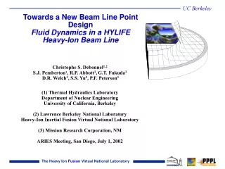
Towards a New Beam Line Point DesignFluid Dynamics in a HYLIFE Heavy-Ion Beam Line Christophe S. Debonnel1,2 S.J. Pemberton1, R.P. Abbott1,G.T. Fukuda1 D.R. Welch3, S.S. Yu2, P.F. Peterson1 (1) Thermal Hydraulics Laboratory Department of Nuclear Engineering University of California, Berkeley (2) Lawrence Berkeley National Laboratory Heavy-Ion Inertial Fusion Virtual National Laboratory (3) Mission Research Corporation, NM ARIES Meeting, San Diego, July 1, 2002
Outline • Towards a new point design • Fluid dynamics • Vortex • Gas Venting • Magnetic shutter
Larger numbers of beams can improve the performance of HIF drivers and targets • Target gain increases with smaller spot size • Using 100+ beams reduces individual beam current, improves focusing • Current LBNL/LLNL/ UCB Point Design project is investigating 112 and 160 beam systems Cut-away schematic of an HIF thick-liquid pocket
A 9x9, 112-beam array has been designed • Beam-line parameters: • beam half angle: 15 mrad • cylindrical jet standoff from beam cone to permit gravity deflection and pointing errors: 5-mm • cylindrical jets have diameter of 90% of the liquid envelope diameter to allow for surface roughness • Array parameters: • 56 main pulse beams, 56 foot pulse beams • spacing between beam array rows: 6° • main pulse • maximum beam angle: 24.7° • minimum beam angle: 18.0 • foot pulse • maximum beam angle: 19.0° • minimum beam angle: 8.5°
9x9 array showing beam tubes and magnets at 6 meters Detailed mechanical design of the beam tubes is needed to determine where steel, coolant, voids, and other materials will be located to allow injection/ extraction of vortex flow and optimize shielding
UCB has improved flibe vapor pressure predictions and identified a new salt composition allowing lower pressures • Detailed activity coefficient data has allowed the vapor pressure of flibe to be accurately predicted at lower temperatures • Ternary salt systems (“Flinabe,” LiF/NaF/BeF2) have been identified with very low melting temperatures (320°C) • Equilibrium vapor pressure (109/cc at 400°C) Recent flibe vapor pressure prediction A degassing system may permit flinabe to be used for He/H2 pumping
Steaty-State Gas Pressure in Beam Tubes • Low-temperature, low vapor-pressure flinabe is a very effective getter • Assuming perfectly absorbing boundaries, density at last magnet (nf) is given by • Where no = ambient density in chamber • Ro = chamber port radius • L = distance from last magnet to chamber entrance • For chamber at ~ 0.1 Pa, L=3m, vacuum in magnetic section can reach 10-4 Pa range
Strategies to Prevent Debris Deposition in the Beam Tubes • Design efficient target chamber structures: Mass and energy fluxes at the entrance of beam ports should be as low as possible • Venting in target chamber has been modeled to determine inlet boundary conditions for the beam tubes • Liquid Vortex or Liquid Vortexes? • Mechanical shutter too slow: Magnetic Sweeper
Key heavy-ion thick-liquid chambers phenomena include gas dynamics and vapor condensation in the target chamber and in the beam tubes
Cylindrical Jet Grids • Beam access requires multiple round beam ports in the target chamber wall • Cylindrical jet grids provide a square lattice of jet liquid
Vortex Tubes • Annular flow in the beam tubes can reduce the apertures in the square lattice to round ports called “Vortex Tubes” • Stable centrifugal flow provides additional protection in the beam lines
Vortex Layer Construction • Formation of the vortex layer requires injection of liquid tangent to the inner pipe wall, directed at some angle q from the pipe axis • An outer flow plenum and an inner wall with many small, properly aligned injection holes provides a good tube
Vortex Tube Operation • Vortex flow is redirected at either end of the vortex tube using suitable extraction sections • The Berkeley tube uses a sudden extraction at the ‘target chamber’ end of the vortex tube, as shown in the figures (left) • Extraction can also be accomplished with many small tubes (a reverse injection), which would maintain electrical continuity in the pipe wall
Bi-directional injection 12 rows x 9 holes / 2 = 54 injection holes in each direction (N) Layer thickness depends only on the injection and pipe radii, not on the injection velocity! The Berkeley vortex’s ideal thickness Tlayer would be 1/6 the pipe radius Injection radius c of 1.2 mm and angle q of 45 deg Vortex Layer Flow
Thickness Measurements • The vortex tube was constructed using transparent PVC pipe. • Masking on the outside of the pipe provided an easy way to measure the vortex layer thickness photographically. • Actual thickness of the Berkeley vortex tube is 28% of the pipe radius • Error ~2% of the pipe radius • Standard deviation ~1% of the pipe radius 3 photographs of the vortex layer at various flow rates, and the empty pipe - darker bands are shadows indicating where the pipe is masked
Annular Vortex Generation for IFE Beam Line Protection is Feasible • Use of annular, centrifugally confined vortex tubes is reasonable for beam lines in thick-liquid IFE target chambers • Ideal layer thickness estimates were insufficient to describe the experimentally observed thickness • However, the actual thickness is within the desired range for IFE • A more involved analysis from turbulent flow theory will be necessary for a more accurate prediction of layer behavior
B LSP Plasma Diversion Simulation • x-y Cartesian simulation. • Box was 30-cm long and 10-cm wide. • H+ ions with a 10-100 eV temperature, 1014 cm-3 density and a 3-9 cm/microsecond forward velocity. • A no-field case and a case with electromagnetic fields and a 0.1 T By field (for x > 15 cm). • The By case shows the plasma is stopped. Moving plasma blob confined by B
Conclusions • Beam tube can be coated with liquid vortex. • TSUNAMI predictions indicate that thick-liquid structures in target chamber should be supplemented by other engineering devices in the beam tubes to prevent debris contamination in the final-focus magnet region. • 2D calculations predict expected plasmas diverted by a moderate strength magnetic field