Download
1 / 20
200 likes | 348 Views
MEG Beam Line Studies. Outline of Topics to be Addressed. Status at the time of the last Review Beam Time April/May 2003 “Z-Branch” Beam Transport Solenoid BTS Future Summary/Conclusions Beam Line Schedule Area Layout. Status at the Last Review. Milestone achieved on schedule

E N D
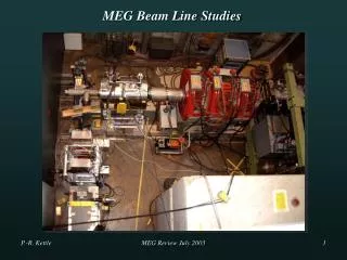
MEG Beam Line Studies MEG Review July 2003
Outline of Topics to be Addressed • Status at the time of the last Review • Beam Time April/May 2003 “Z-Branch” • Beam Transport Solenoid BTS • Future • Summary/Conclusions • Beam Line Schedule • Area Layout MEG Review July 2003
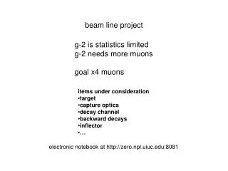
Status at the Last Review • Milestone achieved on schedule • Viable Solution for the MEG Beam Line FOUND • using “Z”-Branch with separate stages for • Particle Separation&Momentum Degradation • via2 triplets+WIEN Filter+ Solenoid/Degrader system • Rudimentary work on Transport Solenoid BTS • had just started • initial length~180cm? with B~0.5T? • Warm or Cold? etc. • Solenoid + Degrader & Stop Distribution measurements • planned • Final part Phase C of “Z”-Branch Measurements • April/May 2003 MEG Review July 2003
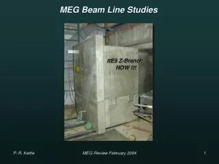
“Z-Branch” Measurements April/May2003 • Measurements: • Phase B – post Triplet 2 & Collimator • Phase C – post Solenoid • Several unexpected problems encountered & Solved !!! MEG Review July 2003
April/May 2003 Beam Test cont. • Total of 4 Weeks • of Beam Time: • 1 week Phase B • 3 weeks Phase C • PROBLEMS: • 3 Days Accelerator Down • Planned for • Solenoid Fringe-field • distorts optics between • Triplet 2/Collimator & Solenoid • Extra vacuum pipe between Collimator & Solenoid SOLVED !!! • WIEN Filter DOWN for nearly ALL Phase C measurements • due to HV-insulation Problems at Cable feed-through (OIL) • Measurements done without Separator FULL e+ beam • NaI found to have NO Magnetic Shielding – solenoid stray field • Built Magnetic Shielding Box SOLVED !!! CONSEQUENCE2-Day -Beam Test Cancelled MEG Review July 2003
Trip. Colli. WIEN Solenoid µ+ µ+ Triplet 2 e+ e+ Filter 1 Results “Z-Branch Measurements” Phase A P-Spectra: -Kinematic Edge (29.79 MeV/c) Theoretical func. P3.5 folded with Gaussian ΔP/P + Const. Cloud µ+ contribution “U-Branch” “Z-Branch” Pcent=(28.2±0.1)MeV/c ΔP/P =(7.9±0.6)% FWHM PBeam=(28.2±0.9)MeV/c Consistent with TURTLE & P-Slit settings/Calib. Integrated Rate 4cm Tg.E @ 1800µA Nµ~1.3·108 µ+/s (2.3·108 µ+/s 6cm Tg.) “Z-Branch” MEG Review July 2003
Trip. Colli. WIEN Solenoid µ+ µ+ Triplet 2 e+ e+ Filter 1 Phase B Separation Quality Phase B Integrated Rate After Separator 4cm Tg.E @ 1800µA Nµ~9.4·107 µ+/s (1.7·108 µ+/s 6cm Tg.) Ne/Nµ > 9 Ne~ 8.7·108 e+/s Transmission Factors TSep= (71±5)% TColli= (90±5)% Low Threshold 50mV µ+ e+ Integrated Rate 4cm Tg.E @ 1800µA Nµ~8.5·107 µ+/s (1.5·108 µ+/s 6cm Tg.) µ/e Separation 11.8cm 7.2σ !!! MEG Review July 2003
Trip. Colli. WIEN Solenoid µ+ µ+ Triplet 2 e+ e+ Filter 1 Phase C Post Solenoid Remember !!! PSC only a Test Solenoid PSC-Solenoid 20cm Bore Beam Line 32 cm Bore Integrated Rate After Solenoid 4cm Tg.E @ 1800µA Nµ~6.1·107 µ+/s (1.1·108 µ+/s 6cm Tg.) Beam Spot: σX ~ 5.3 mm σY~ 6.5 mm Transmission Factor Solenoid TSol= 71 % Single Node SNM Double Node DNM Previous Excitation Curve DNM confirmed DNM focus Z0 14.53 A Previous U-Branch 14.56 A With larger Bore i.e. BTS T>71% MEG Review July 2003
e+ Foils CH2 at focus Solenoid µ+ CH2 Tg Fix Degrader Var. Tg Degrader & Stopping Distribution Measurements Target Thickness vs. NaI Rate Michel Range Curve using NaI: AIR VAC R ~ 870 µ CH2 Degrader Target Target 88% stopped in 400µ CH2 Tg. Measurement Simulation Fix Degrader 600 µ Geant say 580µ Nearly all Stopped in 400µ • GivesRMean = 1150µ • Equiv GEANT + TRIM • 88% STOP in 400µ Tg !!! MEG Review July 2003
Beam Transport Solenoid BTS Design in conjunction with Novosibirsk + PSI Magnet Group + Tokyo Superconducting solution Chosen Present Design under study LCRYO = 2800 mm LCOILS = 2630 mm DBORE = 320 mm BCENT = 0.347 T Optics + further simulations underway COBRA BTS COBRA BTS MEG Review July 2003
Future • Priorities: • Finish simulations for design BTS end July • Complete BTS Design together with Novosibirsk, PSI, Tokyo • Manufacture + Delivery by late Spring 2004 • Start Design for new Triplet 1 Wagon + Quads (µE4 Beam) • ready for Insertion Shutdown 2003/2004 • Start Design of Target System for Experiment & choose optimal • Degrader positioning • Continue Data Analysis of Beam Data • New vertical Separator requested ( MEG, µLAN, µSR) • vertical WIEN Filter MANDATORY for MEG MEG Review July 2003
Summary/Conclusions • Satisfactory Beam Line Solution has been achieved for MEG • with a complete test of components up to COBRA injection • Separator Transmission of (71±5)% achieved • Rate of 8.5·107 µ+/s at 1.8mA with 4cm Target at I/P Solenoid • (1.5·108 µ+/s at 1.8mA 6cm Tg Proposal) • µ/e Separation of 11.8cm at Collimator 7.2σ achieved • Using a small Bore Solenoid a Transmission of 71%obtained • rate 6.1·107 µ+/s at 1.8mA with 4cm Target • (1.1·108 µ+/s at 1.8mA 6cm Tg PROPOSAL!!!) • Spot-size post Solenoid of σX=5.3mm, σY=6.5mm achieved • equivalent to spot-size in Proposal at Target • 88% of ALL µ+STOPPED in Thin Target of PROPOSAL • Lots more work still needed e.g. BTS, Target System MEG Review July 2003
BTS Time Schedule Beam line 2002 2003 2004 2005 Studies Solenoid BTS Milestone Choice “U”/”Z” + Method Triplet 1 Target Milestone Design Manufacture Assembly Test 2003: January February March April May June Shutdown Beam Line Commission- ing starts Insertion Triplet 1 COBRA installation PMC + Laser Hut + Sindrum 2 removal MEG Review July 2003
E5 Area Layout Following Slides from Stefan Ritt MEG Review July 2003
Ideas for pE5 area • Permanent installation of MEG experiment • Concurrently run other experiments • No need of rail system if • Beam line elements are removed • Concrete wall in front of MEG detector • COBRA + most electronics on platform • LXe storage tanks on separate platform • Calorimeter on small rail system • 500 kg crane on top of platform • “curtain” and A/C around platform MEG Review July 2003
Trigger & DAQ optional wall electronics HV small rail LXe storage compressor LN2 line Area Layout MEG Review July 2003
RACKS COBRA floor cover (removable) 100 150 “double floor” Platform Design MEG Review July 2003
crane removable cover (wood) COBRA LXe Calorimeter curtain (transparent plastic) MEG Review July 2003
signal HV HV DRS HV splitter fiber DRS splitter Electronics MEG Review July 2003
Current design status (June 24th) MEG Review July 2003