Download
1 / 32
320 likes | 445 Views
Positron polarization at the ILC: RDR vs. SB2009. Sabine Riemann, DESY Zeuthen International Workshop on Linear Colliders 2010, Geneva October 25-29, 2010. Outline.

E N D
Positron polarization at the ILC: RDR vs. SB2009 Sabine Riemann, DESY Zeuthen International Workshop on Linear Colliders 2010, Geneva October 25-29, 2010
Outline S. Riemann Positron polarisation = upgrade option for ILC, CLIC. Nevertheless, the undulator based ILC design will provide polarized positrons from beginning (~22%…35% ). Up to now no clear strategy has been mediated what to do with this polarized positrons • Why positron polarization ? • Positron polarization • in RDR • in SB2009 • Physics goal of low positron polarization ? What to do with low positron polarization ? • Summary
FLC – the precision machine Goal of a Future Linear Collider: Observe, determine and precisely reveal the structure of the underlying physics model Needed: • High energy • High luminosity precision • Polarization knowledge of initial state Experimental flexibility be prepared for the unexpected The electron beam of a future LC will be polarized. Lessons from LEP/SLD sensitivity to parity violating couplings • Unpolarized beams (LEP, 17x10^6 Z events) AFBdsin2qeff = 1.2x10E-3 • Polarized beams (SLC, 5x10^5 Z events) ALR dsin2qeff = 1.2x10E-3 What about polarized positron? • positron polarization is not the Baseline Design of ILC or CLIC • Physics goals are summarized in Moortgat-Pick et al.,Phys.Rept.460(2008)131 S. Riemann
ILC Baseline Machine (RDR) Physics between 200 GeV and 500 GeV Electrons: P > 80% Energy stability and precision below 0.1% Luminosity: Year 1-4: Lint = 500 fb-1: 1. year 10% Lint≈ 50 fb-1 2. year 30% Lint≈ 150 fb-1 3. Year 60% Lint≈ 300 fb-1 4. year 100% Lint≈ 500 fb-1 expected statistics: few 104 ee HZ at 350 GeV (mH≈120 GeV) 105 ee tt at 350 GeV 5·105 (1·105) ee qq (mm) at 500 GeV 106 ee WW at 500 GeV • statistical cross section uncertainties at per-mille level !! (after 1st year ~ 1% level) O(10-3) S. Riemann
e+e- initial states SM g, Z, Z’ ,… J=1 J=0 S. Riemann
s-channel processes SM ±Pe+, ±Pe- enhancement or suppression of sij S. Riemann
Polarized initial states: e+e- m+m- R-parity violating SUSY (spin-0) or Z’ (spin-1) ? enhancement for e+(L)e-(L) enhancement for e+(L)e-(R) (see also POWER report) e+ polarisation improves sensitivity substantially 30% 22% S. Riemann
s-channel processes • Cross section measurements: enhancement of SM contributions by factor 1-Pe-Pe+ • e.g. LC as Higgs factory (Higgsstrahlung) enhancement of effective luminosity • (±80%,±60%) 1.48 dstat improved by 22% (±80%,±34%) 1.27 dstat improved by 13% (±80%,±22%) 1.18 dstat improved by 8% • Effective polarization Peff • Higher than e- polarization, but this becomes less important for P(e-) >90% • Uncertainty of effective polarization is substantially smaller, dPeff < dPe- S. Riemann
Peff Positron polarization increases effective polarization: For comparison: first LC studies: (60%,40%)Peff=0.8 S. Riemann
D Peff • Decrease of error on Peff (error propagation) (80%,60%) dPeff = 0.25 dPe- (80%,22%) dPeff = 0.75 dPe- (80%,34%) dPeff = 0.50 dPe- dPe-/Pe- = d Pe+ /Pe+ = 0.25% (see ILC-NOTE-2008-047) dP/P ~O(10-3) S. Riemann
Why positron polarization ? (contd) • u,t-channel: helicities of initial and final state are directly coupled, but independent of the helicity of the second incoming beam particle • Single W production vertex depends only on P(e+) S. Riemann
Transverse polarization • sensitivity to new physics (CP violation, graviton) • does NOT work with e- polarization only • e+ polarization 60% 22% effect is decreased by factor 3 More scenarios (KK, Z’, spin discrimination) see talk of Tom Rizzo Rizzo MH=1.5 TeV, E=500 GeV, L=500 fb-1 Graviton exchange (ADD model) S. Riemann
WW production suppression of t-channel contribution by chosing the polarization of the initial stat Simultaneous fitting of TGC’s and polarization (e+ and e-) see talk by Ivan Marchesini S. Riemann
ILC undulator based e+ source is polarized P(e+) is useful – but is it indispensable for a future linear collider? • Up to now we have not yet obtained new signatures that cannot be studied without positron polarization • new physics signals are expected at the LHC; they can be interpreted with substantially higher precision if positron polarization is available distinction of new physics models • Z factory “GigaZ” (10^9 Z bosons) is impossible without e+ polarization LC Design may not prevent a polarized positron beam S. Riemann
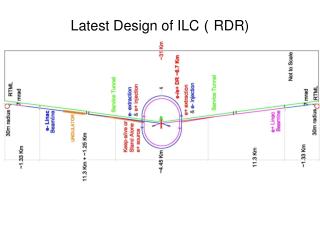
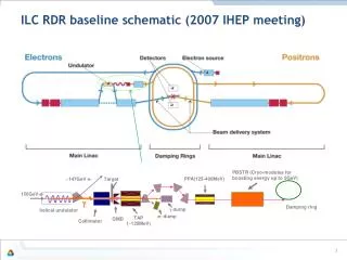
Under condsideration: Strawman Baseline design 2009(SB2009) Sc. Helical Undulator Located at end of electron linac (125…250 GeV) 231 m long, aperture 5.85mm Capture Quarter wave transformer (QWT) lower e+ yield Auxiliary Source 3 GeV e- beam to positron target RDR (2007) Sc. Helical Undulator Located at the 150GeV point in electron linac l = 1.15cm, B=0.86T (K=0.92) 147m, aperture 5.85mm Target Ti Alloy wheel radius 1m, thickness 1.4cm Rotating speed 100m/s (2000rpm) Capture Flux concentrator (FC) Keep Alive Source (KAS) Independent, conventional 10% intensity ILC Positron Source Layout Spin rotator S. Riemann
Yield of Polarized Positrons at ILC Helical undulator, RDR design e+ polarization ~34% no photon collimator SB2009 e+ polarization ~22% distance undulator target: 400m SB2009 Proposal Document: Is Pe+ =22 % sufficient or annoying for physics? S. Riemann
Comparison RDR SB2009: e+ polarization undulator length better positron capture using flux concentrator than quarter wave transformer to achieve high photon yield SB2009 S. Riemann
ILC positron polarization for physics Need: • Spin rotation upstream e+ damping ring (longit. vertical), and downstream turnaround (vertical longit.) • Need facility for fast helictity reversal to achieve the desired initial states (+ -, -+) • Undulator source ‘+’ or ‘-’ circularly polarization of photons depending on direction of helical windings Fast kicker with 2 spin rotation lines (K. Moffeit et al., SLAC TN-05-045) • e+ Compton polarimeters at IP (desired up- and downstream) • But also zero positron polarization has to be confirmed S. Riemann
No ILCpositron polarization ? • Destroy the 22%÷34% positron polarization • Need facility to depolarize e+ beam (damping ring is NOT sufficient!) • Need precision polarimeter to confirm zero polarization at IP • Use planar undulator • Planar instead of helical undulator transversely polarized photons unpolarized e+ (e-) beam • Photon yield of helical undulator is factor 1.5…2 times higher than that of planar undulator • Conventional positron source (unpolarized e- to target) • Intense beam is a huge challenge for positron production target • Several e+ targets – beam stability at the 0.1% level???? • Polarization upgrade using helical undulator difficult • Reduced physics goal of the LC although we can do it much better!! S. Riemann
Alternative: Compton backscattering (neither at CLIC nor at ILC foreseen as baseline) • ILC time structure special effort • Feasibilty Conclusion: • Undulators are widely used, • proof-of principle experiment (E166) confirmed method • ILC undulator prototyp is constructed, • Should use low e+ polarization (>30%) for physics • If SB2009 should be baseline, polarization upgrade as soon as possible (desired almost from beginning) S. Riemann
Summary • Positron polarization • is important for the physics goal • will be available from the beginning if the helical undulator is baseline design should be used for physics, also if pol upgrade (photon collimator) necessary • Milestones: • ILC: Technical Design Report end 2012 • CLIC: CDR in 2011 e+ polarization has to be covered in these reports • Still to do – for ILC and CLIC: • Realistic scenarios with polarization and consequences for physics precision • Realistic spin tracking from start to end • Depolarization effects at IP • Demonstrate target reliability • Demonstrate that the flux concentrator will work (higher e+ yield) … and detection of signals beyond the SM Positron polarization needs more attention from machine and physics groups to be prepared for the unexpected S. Riemann
Thank you ! S. Riemann
BACKUP S. Riemann
Polarized Positrons from Helical Undulator • Rotating dipole field in the transverse planes • Electrons follow a helical path • Emission of circularly polarized radiation • Polarization sign is determined by undulator (direction of the helical field) • # photons ~ undulator length • Photon yield in a helical undulator is about 1.5…2 higher than that in a planar undulator (for the parameters of interest) Opening angle of photon beam ~1/g (first harmonic) See also Mikhailichenko, CLNS 04/1894 S. Riemann
Location of sources at the ILC RDR: SB2009 S. Riemann
Comparison of RDR and SB2009 e+ source parameters S. Riemann
Positron polarization Positron spectra RDR Undulator, distance undulator – target ~500m Average positron polarization (~34% for RDR design) • With photon collimator upstream the target: increase of polarization • decrease of positron yield longer undulator photon beam size [mrad] S. Riemann
Positron Target • Material: Titanium alloy Thickness: 0.4 X0 (1.4 cm) • Incident photon spot size on target: s ~ 1.7 mm (rms) (RDR) ~ 1.2 mm (SB2009) • Power deposition in target: 8% 10.4 kW (RDR); <8 kW (SB2009) But peak energy deposition density is higher for SB2009 design • Rotate target to reduce local thermal effects and radiation damage 2m diameter target wheel, 2000 rpm • Issues to be resolved and the solutions validated: • Stress in target material, pressure shock wave impact on target lifetime • rotating vacuum seals to be confirmed suitable S. Riemann
Positron yield Optical matching device OMD: Increases capture efficiency from 10% to as high as 40% • Adiabatic Matching Device (AMD): • Tapered B field from ~5 T at the target to 0.5 T in 50 cm • Capture efficiency >30% • Rotating target immersed in B field eddy currents • Eddy current experiment @ Cockroft Institute expect 8 kW at 2000 rpm heat load on target substantially increased B Z Target position S. Riemann
Optical Matching Device (2) • Flux Concentrator (FC) • Flux concentrator reduces magnetic field on target but lower captureefficiency ~22% • RDR design with FC • pulsed flux concentrator (used at SLD): • ILC needs ~ 1ms pulse width flat-top • LLNL: Design and prototype (budget): Target position S. Riemann
Optical Matching Device (3) • Quarter Wave Transformer (QWT) • QWT is a save solution • but capture efficiency is ~15 % • SB2009 design with QWT Length of helical undulator 231m • upgrade to P(e+) = 60% would make the undulator so long that photon powers become worrying and electron energy loss very high better to use a flux concentrator S. Riemann
WW production suppression of t-channel contribution Suppression factors for t-channel in comparison to unpolarized beams S. Riemann