Download
1 / 30
300 likes | 322 Views
The International Linear Collider Accelerator R&D Program. Steve Holmes Fermilab Associate Director for Accelerators EPP2010 May 16, 2005. Outline. ILC Orientation Technology Requirements and Challenges Risk Elements R&D Program Fermilab Perspective Summary. 308 ns. e +. e -.

E N D
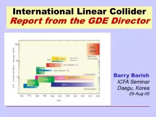
The International Linear ColliderAccelerator R&D Program Steve Holmes Fermilab Associate Director for Accelerators EPP2010 May 16, 2005
Outline • ILC Orientation • Technology Requirements and Challenges • Risk Elements • R&D Program • Fermilab Perspective • Summary
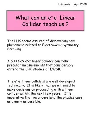
308 ns e+ e- 250 GeV 250 GeV ILC OrientationWhat is it? • A facility for providing electron-positron collisions at sufficient energy and luminosity to afford access to the physics frontier at and beyond LHC. • Requirements: • Energy = 500 GeV, extendible to 1000 GeV • Luminosity ~ 21034 cm-2sec-1 (500 fb-1 in the first four years) • How? 7 nm
ILC OrientationWhat does it look like? • Major Components: • Sources: Provide particles ( e+ generated by electrons) • Damping Rings: Reduce emittance • Bunch Compressors: Reduce bunch length • Linac: Accelerate • Beam Delivery/Final Focus: Prepare, focus, and collider • Detector(s): Observe Length = 40-50 km
ILC Orientation International/National Scene • The International Linear Collider has received strong endorsement by HEPAP, and corresponding advisory committees in Europe and Asia, as the next forefront EPP facility beyond LHC. • ILCSC established and functioning • Under auspices of ICFA • Charge: Promote construction of a linear collider through world-wide collaboration • Global Design Effort (GDE) established: B. Barish/Director • USLCSG established and functioning. • Charge: Coordination of U.S. R&D activities; • Preparation of the U.S. bid to host • Identification of LC as highest mid-term priority in the Office of Science 20-year plan
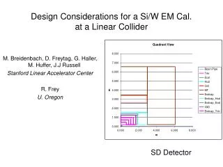
RF Accelerating Structures Accelerating structures must support the desired gradient in an operational setting and there must be a cost effective means of fabrication. ~17,000 accelerating cavities/500 GeV Current performance goal is 35 MV/m, (operating at 30 MV/m) Trade-off cost and technical risk. ILC Requirements and ChallengesEnergy: 500 GeV, upgradeable to 1000 GeV ~Theoretical Max Cost 1 m Risk
Progress over the last several years has been in the area of surface processing (electro-polishing) and quality control. Several single cell cavities at 40 MV/m (alternative shapes) European XFEL design goal of 28 MV/m ~1000 cavities fabricated over 2006-2011 ILC Requirements and ChallengesEnergy: 500 GeV, upgradeable to 1000 GeV • Accelerating Structure Status • All high gradient 1.3 GHz accelerating cavities produced to date have been fabricated (by European industry) and tested by the TESLA collaboration. • Roughly 80-100 cavities • >15,000 hours operation in the TESLA Test Facility (TTF) at DESY (Hamburg): two 8-cavity cryomodules @ ~16 MV/m • Five nine-cell cavities have tested successfully at >35 MV/m
ILC Requirements and ChallengesEnergy: 500 GeV, upgradeable to 1000 GeV • RF power generation and delivery • The rf generation and distribution system must be capable of delivering the power required to sustain the design gradient: • 10 MW 5 Hz 1.5 msec • ~700 klystrons and modulators/500 GeV • The rf distribution system is relatively simple, with each klystron powering 30-36 cavities. • Status • Klystrons under development by three vendors (in Europe, Japan, and U.S.) • Three units from European vendor (Thales) have come close to meeting spec. • Sheet beam under development at SLAC (cost reduction) • Modulators meeting performance spec have been built and operated (at TTF) for the last decade.
Note critical role ofey (db=3-5%) ILC Requirements and ChallengesLuminosity: 500 fb-1 in the first four years of operation The specified beam densities must be produced within the injector system, preserved through the linac, and maintained in collision at the IR. • Sources • 80% e- polarization • ~1e+/e-; polarized? • Damping Rings • ex/ey = 8.0/.02 mm • Emittance preservation • Budget: 1.2 (horizontal), 2 (vertical) • Maintaining beams in collision • sx/sy = 540/6 nm
ILC Requirements and ChallengesLuminosity: 500 fb-1 in the first four years of operation • The required emittances, ex/ey = 8.0/.02 mm, have been achieved in the Accelerator Test Facility (ATF) damping ring at KEK. However: • Single bunch, e- • Normalized, not geometric emittance • Circumference = 138 m (vs 6-17 km required for superconducting ILC) • Emittance growth budget from DR to IR is 1.2 (H), 2.0 (V): • Growth: wakefields, alignment, and jitter • Control is through “BNS damping” (wakes) and dynamic alignment control (alignment & jitter, ~300 mm, 300 mrad tolerances) • Collisions: • Final Focus Test Beam (SLAC) achieved required de-mag, but 10 beam size • Intra-train feedback is required to maintain beams in collision
ILC Risk ElementsTechnical Performance/Energy Energy = Gradient Length • Cavity gradient • Will the operating gradient be sufficient to support the energy goal? • Potential mitigations • Establish realistically achievable gradient goal, based on modest extrapolation from current experience, consistent with fundamental limitations (~50 MV/m); • Design with operating margin relative to gradient goal; • Install over capacity within the facility (~5%); • Construct unfilled tunnel • (Length—little risk the facility will come out shorter than designed!) Assessment: Not the most serious risk. Risk reduction amendable to $$.
ILC Risk ElementsTechnical Performance/Luminosity Luminosity= ∫L dt • Peak Luminosity (L) • Significant extrapolation from experience base: ~104 SLC • Emittance capabilities of the source (esp. damping rings) • Emittance preservation in the linac • Maintaining nm beams in collision • Detector backgrounds • Potential Mitigations • R&D on feedback, feedforward systems • Integrated simulations • Well characterized wakefields and alignment capabilities • Well characterized, quiet site • “Headroom”/alternative routes (parameter sets) to same luminosity Assessment: Luminosity goals are very aggressive (driven by physics requirements) and represent significant risk.
ILC Risk ElementsTechnical Performance/(Integrated) Luminosity Luminosity= ∫L dt • Availability (∫dt) • Goal is 75% availability (actual/scheduled operations) • Requires component mean time between failures (MTBF) typically a factor of 10 beyond current experience (~106-7 hours). • Requires protection against beam “accidents” • ~2 MJ per beam pulse (comparable to Tevatron, but smaller beam) • Potential Mitigations: • Operational modeling (complexity comparable to the Tevatron) • Design up front for high MTBF • Fail safe Machine Protection System • Redundant systems/installed overhead Assessment: Availability goals are aggressive for a facility of this complexity and represent significant risk.
Can a reliable cost estimate be developed? Significant experience base with components representing ~50% of cost: Conventional facilities, cryogenics, magnets, vacuum, controls systems Balance represents significant extrapolation: Accelerating structures, rf sources, systems integration, beam delivery Savings for quantity production extrapolated to lie in the range 3-5 for accelerating structures fabrication. Potential Mitigations: Well defined and controlled scope Complete systems testing, technology transfer, demonstrated industrial capabilities and production models prior to construction start Multiple component streams Scope reduction strategies/scenarios identified up front Assessment: Will have much better handle with CDR release. ILC Risk ElementsCost Performance
ILC R&D ProgramStrategy The purpose of the R&D program is to reduce risk. • All risk elements need to be addressed in the pre-construction R&D program: Technical, Cost, and Schedule performance. • Strategy • Target critical performance and cost risk elements • Systems simulations based on characterizations from prototype components • Major demonstration projects to validate assumptions • Program Elements • Preparation of a conceptual design (CDR), supported by subsystem R&D • Construction and testing of prototypes • Technology transfer and industrialization • Integrated systems testing • Development of plans for conventional facilities and infrastructure • Preparation of a final site-specific engineering design. • Preparation of regional hosting proposals ~Time
Oversight ILCSC GDE - Director ILC-Asia ILC-Europe ILC-Americas Regional Team Regional Director and Deputy Institutional ILC Managers for major instiutional members USLCSG communications Regional Funding Agencies FNAL ILC-FNAL Manager SLAC ILC-SLAC Manager TRIUMF ILC-Canada Manager Cornell ILC-NSF PI Lead Labs WP 1.FNAL WP 2.SLAC NSF-funded Institutions Work Package WP 1.ANL WP 2.BNL Canadian Institutions WP 3.FNAL WP 3.SLAC ILC R&D ProgramInternational/Regional Organization International Regional
ILC R&D ProgramAmerican Organization • Major initiatives & test facilities (US) • Significant presence within all major subsystems • Superconducting Module Fabrication and Testing Facilities • Industrialization (more advanced in Europe than US/Asia) • Integrated systems test (linac) • Modeling/simulations • Site Development • Overseas • TTFII • EuroTev • ATF • STF
ILC R&D ProgramResource Requirements • The USLCSG model shows (through site specific engineering design): • $650M (internationally shareable) costs • US share = $220M • $300M of US bid-to-host and pre-construction activities (assumes success) • Total US expenditure ~$500M • Accelerator scientist/engineer resources within this are estimated at: • ~400 person-years (total, American share) • ~150 FTE (peak, American share) • Currently available AS/E resources within the USHEP program: • ~70 FTE – currently working on ILC R&D • ~140 FTE – currently engaged in accelerator operations (Tevatron, PEP-II, CESR); all scheduled to cease operations over 2008-2010. • Resources exist to execute the ILC R&D program without having to tap into other labs. Dave: how much of this is BTH and how much LLP?
ILC ConstructionResource Requirements • The TESLA TDR estimated ~1400 person-years of accelerator scientist/engineers to construct. • USLCTOS viewed this as a credible estimate. • ~250 FTE (peak, world-wide) • US share (if host) ~150 FTE • Well matched to the complement on hand at the end of the R&D program • Significant resources exist in non-HEP labs which could back this up subject to other programmatic goals (in US and abroad) • (~100 accelerator physics grad students in the DOE system at end of 2003). Bottom line: The accelerator scientists and engineers needed to execute the ILC R&D and construction programs exist within the HEP program or are in the pipeline. Whether they will be available at the start of construction depends upon continuity of support.
Fermilab and the ILC Long Range Plan • The Fermilab Long Range Plan establishes the ILC as the primary goal for Fermilab in the coming decades, with a world-leading neutrino program as the goal if the ILC were delayed or constructed elsewhere. • The cold technology decision has allowed close alignment of Fermilab’s R&D programs in support of these goals. Fermilab is pursuing ILC and “Proton Driver” R&D, in parallel, based on superconducting rf technologies.
Fermilab and the ILCFermilab as Host • The FLRP advocates preparation of a Fermilab bid to host an international linear collider project and identifies attributes that we believe make Fermilab/northern Illinois very attractive as potential host: • Fermilab • Scientific and engineering expertise in forefront accelerator technologies • Significant experience in construction and operations of large accelerator projects • The leadership mantle of U.S. high energy physics • Northern Illinois • Strong scientific base, including two national laboratories and five major research universities • Geology ideally suited to a linear collider • Transportation and utilities infrastructure system that could support LC construction and operations. DOE/SC has identified Fermilab/northern Illinois as the preferred U.S. site. Am checking with Robin to confirm he is onboard with this.
Leadership of the America’s regional effort in development of the scrf technology base for the ILC. It is imperative to establish US-based capability in the fabrication of high gradient superconducting accelerating structures if the US is to compete to host. Significant U.S. SCRF expertise at: Argonne, Cornell, Fermilab, Jefferson Lab, Los Alamos, Michigan State. Experience extends to both development and fabrication (e.g. SNS), but at gradients significantly below 35 MV/m (SNS cavity fabrication by European vendor). Fermilab is establishing facilities for the fabrication and testing of US-produced ILC superconducting modules with US and international partners. Leveraging our significant infrastructure and scientific/engineering resources. Fermilab and the ILCR&D Strategy
Fermilab and the ILCR&D Strategy • Significant contributions to the understanding of beam dynamics issues: • Low emittance transport through the linac • Damping ring design • Machine/detector interface issues • (USLCSG) Bid to host • Site studies and characterization • Public outreach Fermilab is currently active in all these areas. The goal is to provide the US with the best possible host site for a prospective ILC bid.
Fermilab and the ILCCryomodule Fabrication and Testing Facilities Fermilab has initiated work on two major facilities for ILC srf technology development: Cryomodule Fabrication Facility Module Test Facility SMTF Collaboration: ANL, BNL, Cornell, FNAL, JLab, LANL, LBNL, MIT, MSU, NIU, ORNL, Penn, SLAC, (CAT, DESY, INFN, KEK)
Motivation: Neutrino "superbeams" High level parameters: 0.5-2.0 MW @ 8 GeV 2.0 MW @ 120 GeV Possible implementations: 8 GeV synchrotron; or 8 GeV superconducting linac The superconducting linac is preferred: Synergy with ILC R&D cavity development, industrialization, systems testing Lower beam emittance Better performance over entire energy range Flexibility for the future Fermilab and the ILCILC Proton Driver Synergies
Fermilab and the ILCILC Proton Driver Synergies • Considerable technology overlap with ILC: • ILC compatible frequencies “ILC” LINAC • Structure development and industrialization
Fermilab and the ILCTimeline/decision tree • Between now until 12/31/06 Fermilab R&D activities are independent of the final destination: • Completion of ILC CDR with supporting R&D • Completion of PD CDR with supporting R&D • A series of branch points then develops in response to the ILC CDR, leading over the balance of the decade to either: • A decision to construct ILC (soon); or • A decision to construct the Proton Driver; or • … • See Pier Oddone’s presentation for details.
Summary • The ILC represents an enterprise at the forefront of both human knowledge and human technical capabilities. • A undertaking worthy of the United States! • ILC performance goals have been established. • Based on >10 years of R&D in U.S., Europe, and Japan • ILC risk elements have been identified and motivate an R&D program supporting a complete engineering design by the end of the decade. • Luminosity goals are more challenging than energy. • CDR will establish an initial cost range at the end of 2006. • The US R&D program is being reoriented in response to the technology decision and in alignment with the international framework. • Fermilab’s R&D program is aligned with US aspirations for the future • SCRF R&D is the unifying technology theme • Fermilab is committed to a leadership role in the ILC R&D program and to preparing itself to host the ILC if/when that decision comes.
References International Linear Collider Steering Committee http://www.fnal.gov/directorate/icfa/International_ILCSC.html U.S. Linear Collider Steering Group http://www.slac.stanford.edu/~hll/USLCSG/ Machine performance specification http://www.fnal.gov/directorate/icfa/LC_parameters.pdf TESLA TDR http://tesla.desy.de/new_pages/TDR_CD/start.html (USLCSG) U.S. Linear Collider Technology Options Study http://www.slac.stanford.edu/xorg/accelops/OptionsReport/LC_opts_full.pdf Technical Review Committee http://www.slac.stanford.edu/xorg/ilc-trc/2002/index.html Fermilab Long Range Plan http://www.fnal.gov/directorate/Longrange/Long_range_planning.html Fermilab ILC http://ilc.fnal.gov/index.html Fermilab Proton Driver http://www-bd.fnal.gov/pdriver/