Download
1 / 1
10 likes | 136 Views
Purpose.

E N D
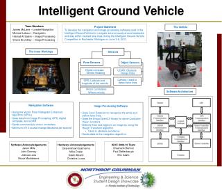
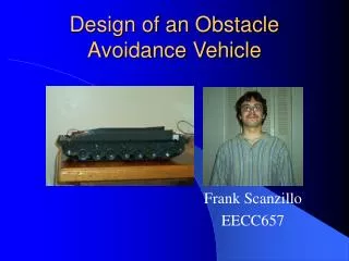
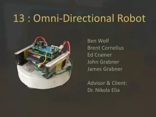
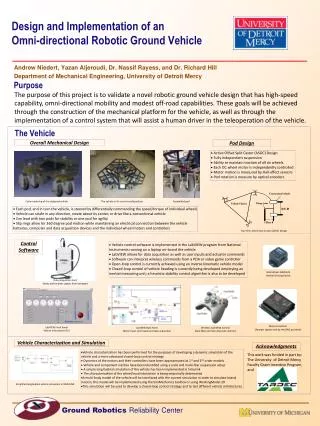
Purpose The purpose of this project is to validate a novel robotic ground vehicle design that has high-speed capability, omni-directional mobility and modest off-road capabilities. These goals will be achieved through the construction of the mechanical platform for the vehicle, as well as through the implementation of a control system that will assist a human driver in the teleoperation of the vehicle. The Vehicle Design and Implementation of an Omni-directional Robotic Ground Vehicle Overall Mechanical Design Pod Design • Active Offset Split Castor (ASOC) Design • Fully Independent suspension • Ability to maintain traction of all six wheels • Each DC wheel motor is independently controlled • Motor motion is measured by Hall-effect sensors • Pod rotation is measure by optical encoders Catia rendering of the designed vehicle The vehicle in its current configuration Assembled pod • Each pod, and in turn the vehicle, is steered by differentially commanding the speed/torque of individual wheels • Vehicle can strafe in any direction, rotate about its center, or drive like a conventional vehicle • Can lead with two pods for stability or one pod for agility • Slip rings allow for 360 degree pod motion while maintaining an electrical connection between the vehicle batteries, computer and data acquisition devices and the individual wheel motors and controllers Top View: Active Spit Castor (ASOC) Design Control Software Andrew Niedert, Yazan Aljeroudi, Dr. Nassif Rayess, and Dr. Richard Hill Department of Mechanical Engineering, University of Detroit Mercy • Vehicle control software is implemented in the LabVIEW program from National Instruments running on a laptop on-board the vehicle • LabVIEW allows for data acquisition as well as user inputs and actuator commands • Software can interpret wireless commands from a PDA or video game controller • Open-loop control is currently achieved using an inverse kinematic vehicle model • Closed-loop control of vehicle heading is currently being developed employing an inertial measuring unit; a heuristic stability control algorithm is also to be developed MicroStrain 3DM-G25 Inertial Sensing Device Data Acquisition Card Sends and receives signals from hardware Motor controller (Accepts signals sent by the DAQ assistant) LabVIEW Front Panel Vehicle Information GUI LabVIEW Back Panel Motor input commands and data acquisition Wireless GamePad Control Xbox 360 controller (top side controls) Vehicle Characterization and Simulation Acknowledgments • Vehicle characterization has been performed for the purposes of developing a dynamic simulation of the vehicle and a more advanced closed-loop control strategy • Dynamics of the motors and their controllers have been approximated as 1st and 2nd order models • Vehicle and component inertias have been identified using a scale and multi-filar suspension setup • A simple longitudinal simulation of the vehicle has been implemented in Simulink • The characterization of the wheel/road interaction is being empirically determined • A multi-body model of the vehicle will be interfaced with the current simulation in order to simulate lateral motion; this model will be implemented using the SimMechanics toolbox or using WorkingModel 2D • This simulation will be used to develop a closed-loop control strategy and to test different vehicle architectures This work was funded in part by: The University of Detroit Mercy Faculty Grant Incentive Program, and Simplified longitudinal vehicle simulation in SIMULINK