Download
1 / 39
430 likes | 635 Views
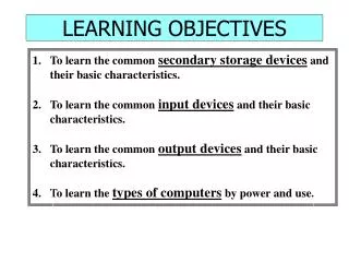
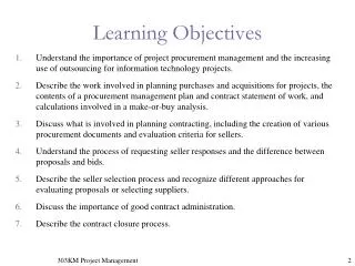
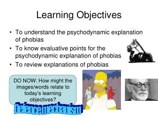
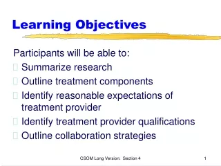
Learning objectives. On conclusion of this part of the subject, the student should be able to : describe how dynamic behaviour is modelled using discrete event processes, and in particular, using events, states and finite state machines describe the concept of sequential finite state machines

E N D
Learning objectives • On conclusion of this part of the subject, the student should be able to : • describe how dynamic behaviour is modelled using discrete event processes, and in particular, using events, states and finite state machines • describe the concept of sequential finite state machines • describe the concept of concurrent finite state machines • understand and apply these concepts in the formal specification of telecommunications protocols
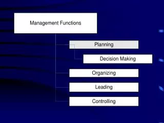
Finite State Machines (FSMs) INPUT EVENTS OUTPUTS input events outputs transition function Transition Function • Finite state machines consist of: current state next state CURRENT STATE NEXT STATE STATE state • States • Input Events (or Signals, or Messages) • Transition Functions • Output Events
input events outputs transition function current state next state state Finite State Machine States • Current State • State which determines the current behavior of the machine • Next State • State which will machine have after processing an input event. Next State can be same as current • Start State • State in which machine will be when created
FSM Transitions input events outputs transition function • Triggered by input events the FSM moves from one state to other based on the Transition Function • Transition Function produces the Output and Next State depending on Current State and Input Event • While in particular state FSM is not active. It is waiting for an input to perform next activity current state next state state
e2/x3 S1 e1/x1 e2/x4 S2 e1/x2 State Transition Diagrams • Used to Visually represent an FSM • Emphasis is on identifying states and possible transitions • Circles represent States • Arrows represent Transitions • ei are inputs • xi are outputs
input events current state next state outputs e1 S1 S2 x1 e1 S2 S2 x2 e2 S1 S1 x3 e2 S2 S1 x4 FSM Tables • Each row of the table is one unique combination of Input Events and Current State • For complete definition of FSM all Event/State combinations shall be provided • Table is another way to represent an FSM with an emphasis on exploring all Event/State combinations • All inputs, states, state transitions and outputs of a FSM can be listed in a Table format
state S1 S2 event X1, S2 X2, S2 e1 X3, S1 X4, S1 e2 FSM Table - Compact Form • Here in the top row of the Table has a list of all States while first column has a list of all Input Event. • Table Field on the intersection represents the transition function for the State, Event combination • Each field contains list of outputs and next state
FSM Example - Telephone • What are possible states • What are possible events • Create FSM Table • Create State Transition Diagram • When we model an object we consider behavior which is of interest for us. • In this case we will consider ability of phone to be used to dial another subscriber, to be used to pass voice between subscribers and to be able to receive incoming calls.
Telephone States • Following States can be identified • IDLE no calls in progress handset is on-hook • DIALING handset is off-hook, but call is not in progress • RINGING handset is on-hook, incoming call alert • PATH ACTIVE handset in off-hook and call is in progress • Relevant events are: • off-hook User takes handset off-hook • on-hook User places handset on-hook • dial digit User dials digit • call alert Exchange alerts phone - incoming call
Telephone - FSM Table Note 1: if last digit in phone number is dialed lower option shall be selected “/“ Unexpected event, “-” No State Change
Off-Hook Stop Ringing RINGING PATH ACTIVE Call Alert Start Ringing On-Hook Dial Digit IDLE On-Hook Dial Digit DIALING Off-Hook Dialing Tone Telephone - State Transition Diagram This is Starting state
Timers & FSMs • Sometimes there is a need to perform some actions after some period of time. For that purpose timers are used • Timers can be started specifying amount of time before time-out will happen • When time-out occurs the timer event will be sent to the FSM. Name of event is typically same as name of timer • Timers can be stopped, so timer event is not generated
Telephone FSM Table with Timers Note 1: if last digit in phone number is dialed lower option shall be selected
Off-Hook Stop Ringing RINGING PATH ACTIVE Call Alert Start Ringing T1 On-Hook Dial Digit IDLE On-Hook Dial Digit DIALING Off-Hook Dialing Tone Telephone STD with Timers Starting/Stopping of the Timers is not visible on STD. This is Starting state
Categories of Finite State Machines • The deterministic FSM defines a machine that performs state transitions only. The transition function is defined for this machine, but not output function. • The Mealy machine has both transition function and output function defined. The machine is the most general case because the output function is determined by both the events, I and the set of states, S . Because of this, input/outputs are attached to the transitions (links with arrows). • The Moore machine is a special case of Mealy machine because the output function is determined only by the set of states, S. Thus, states/outputs are attached to the states instead of the links.
Extended Finite State Machines - EFSM • For more complex problems number of states can increase to be unmanageable - this is called State Explosion • Number of states can be reduced by introducing the local variables. They reduce number of states by hiding less important information • Global state of an EFSM is dependant on the explicit State and current value of its variables. • Generally the information which doesn’t have strong impact on behavior shall be represented as a variable
Extended Finite State Machines - EFSM • EFSM introduce notions of • Tasks where values of Variables are assigned • Decisions where action (output, new state) depends on the Variable value • Starting and Stopping of Timers also represents a task in EFSM
input events current state next state tasks outputs state S1 S2 t1 event e1 S1 S2 x1 T1, X1, S2 X2, S2 -- e1 S2 S2 x2 e1 t3 e2 S1 S1 -- t3, S1 T4,X4,X2, S1 e2 t4 e2 S2 S1 x4,x2 Extended FSMs Table • State tables for EFSM processes should include a separate tasks column, as outputs column is used explicitly for messages that shall be sent
Example of Extended FSM • Communication protocol may rely on message acknowledge mechanism to indicate successful transmission of the message Transmitter Receiver msg User A msg msg User B msg_Ack
EFSM Example • If message is not acknowledged it is re-transmitted Transmitter Receiver msg User A Msg Message lost Msg 1 sec timer expired msg Msg_Ack User B
EFSM Example • If second re-transmission is not acknowledged an error is indicated to user Transmitter Receiver Message lost msg User A Msg 1 sec timer expired Msg Message lost error_Ind 1 sec timer expired
EFSM - States, Events • Consider Transmitter - what states can be identified • IDLE no acknowledge pending, ready to send next message • W4_ACK waiting for acknowledge of next message • What Input Events can be identified • msg From user • Msg_Ack From Receiver • What Output Events can be identified • Msg to Receiver • error_Ind to User
EFSM State Table State Event
Equivalent FSM State Table State Event
Modelling of Complex Systems • So far we have only considered a single FSM • Typical Telecommunication System to complex to be represented with a single FSM. • As usually when dealing with complexity we should split a complex problem in a number of smaller components • In this case we will have number of concurrent FSMs communicating with each other • The two communication mechanisms for concurrent processes can be categorised into Message Passing and Shared Data
Communicating FSMs • Communicating FSM can be • in a single process (task, thread of control) • in separate concurrent processes on same microprocessor • on separate microprocessors communicating to each other • Depending how FSMs are co-located different methods of communications are possible (message passing, shared memory, …)
Process Process Send Channel Receive Shared Memory Write Read Process Process Communication Mechanisms for Concurrent Systems • Message passing involves sending and receiving messages through a channel • In the Shared Memory Approach memory is common to both processes, and they can read and write to the memory • The two are equivalent. We will only consider message passing as more general.
Asynchronous & Synchronous Communication • There are two approaches to implementing message passing: Synchronous & Asynchronous • In Synchronous Communication • the processes involved in communication are required to participate at the point of communication simultaneously. If Process A attempts to send a message and Process B is not ready to receive it process A must wait until Process B is ready.
Asynchronous Communication • In Asynchronous Communication • the processes involved in communication are not required to participate at the point of communication simultaneously. • If Process A attempts to send a message and Process B is not ready to receive it sends it anyway. • If process B is ready to receive a message and A has not sent it process B must wait. • Asynchronous communication requires the use of buffers to store messages • All of the protocol specification methods studied in this course will be based upon Asynchronous Communication
Asynchronous Communication using FIFOs • In most communicating systems, a FIFO (First In First Out) discipline is enforced on sending and receiving messages. • During a send event the a message is appended to the end of the queue while a receive event removes a message from the front of a queue. • It is possible to modify the communications channel to provide additional communication constructs such as priority signals. • To absorb any delay variation in the communications channel, FIFOs are usually used at the interfaces.
Send Receive FIFO CHANNEL Process Process Send Receive FIFO CHANNEL Asynchronous Communication using FIFOs
Communicating FSMs • Now consider a model for communicating finite state machines. • Each process can be defined by a set of states. • The process waits in a state for an event to occur. • Messages are received as events by the receiving FSM. • When this input event occurs, it transitions to another state, and in doing so can send out messages and performs other tasks. • This model is the model used by the ITU Specification and Description Language (SDL)
S11 S21 S12 S22 Communicating FSMs - Example Y FSM1 FSM2 Receive(X)/ Send(P) Receive(Y)/ Send(R) Receive(P)/ Send(Y) Receive(R)/ Send(X)
FSM1 FSM2 Y R X P Y Communicating FSMs - Example After receiving event Y FSMs will continue to oscillate indefinitely between their two states
Benefits of the Communicating FSM model • The overall state of the system can be described by a vector of all the states of the individual processes. • The overall system state itself becomes a finite state machine, and thus its behaviour becomes more deterministic.
FSMs - Summary • Discrete event processes and finite state machines are key concepts in modelling the dynamic real-time behaviour of telecommunications software. • FSM consist of • States (Initial, Current and New) • Input Events • Output Events • In case when “state explosion” is an issue extended FSM (EFSM) may be used so some states are replaced by local variables • Complex Telecommunication Systems can be modelled as number of communicating FSMs
Protocol Specification & FSMs • Many Formal protocol methods are based upon Finite State Machines. • The ITU Specification and Description Language (SDL) is one such formal specification method • Most protocols defined by ITU after the advent of SDL are described using SDL. • Prior to the introduction of SDL protocols were described using a variety of different methods including natural language.
Protocol Specification & FSMs • Even with the advent of formal specification languages there still exist ambiguities and incompleteness in the protocol specifications that must be resolved in the software design • Even formally specified protocols may not have been validated sufficiently. • The standards don’t include machine dependent details (like create application process) leaving the software designer to fill the gaps in.