Download
1 / 109
1.09k likes | 1.12k Views
Detailed overview of the design requirements, reaction loads, electrical specifications, and assembly process for the NCSX TF Coil. Includes key elements like wedging, preloads, and support structures.

E N D
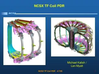
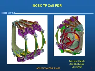
NCSX TF Coil FDR Michael Kalish Joe Rushinski Len Myatt NCSX TF Coil FDR 8/12/05
Outline • Requirements • Design • Review Issues / Chits • Analysis and Test • Fabrication • Summary NCSX TF Coil FDR 8/12/05
Requirements • The TF coils will be designed to meet the requirements of all the reference scenarios. [Ref. GRD Section 3.2.1.5.3.3.2] • 1.7T Ohmic Scenario: 1.7 T for 0.44 seconds , 120 kA Ip1.7T • High Beta Scenario: 1.7 T for 0.44 seconds , 175 kA Ip2T • High Beta Scenario: 2 T for .20 seconds, 200 kA Ip320kA • Ohmic Scenario: 1.7 T for 0.51 seconds, 320 kA Ip15 minute repetition interval between pulses • The TF coils shall be designed to provide a self-field of 0.5T at 1.4m with the current waveform defined for the 0.5T TF Scenario defined in Section A.3.2 of the GRD. • Design Life • 13,000 cycles per year • 130,000 cycles per lifetime • 10% of lifetime or 13,000 cycles for .5 Tesla operation NCSX TF Coil FDR 8/12/05
Requirements • Reaction Loads • In Plane EM reacted by wedging • Out of Plane EM and Gravity by structure • Radial pre-load required to ensure wedging • Tolerance / Location • Global requirement is that toroidal flux in island regions shall not exceed 10% • In plane installed perturbations less than +/- 3mm inboard and +/- 6mm outboard • Out of plane installed perturbations less than +/- 3mm • Leads and Transitions must have a less than 1% effect on toroidal flux in island regions • Shall be up-down symmetric • Mid plane shall be aligned horizontally with the modular coils at 80K NCSX TF Coil FDR 8/12/05
Requirements • Electrical • TF Coils in Series • Voltage standoff to resist maximum operating voltage of 4KV • Maintenance Test, Manufacturing Test, and Design Standoff formulas defined • Design Voltage Standoff to ground is 20KV • Cooling • Pre-Pulse Temp 80K • System pressure adequate to guarantee single phase flow • Pulse repetition rate shall not to exceed 15 minutes NCSX TF Coil FDR 8/12/05
Design • Requirements • Design • Overall Design • PDR Design Upgrades • Interference Evaluation • Insulation Scheme • Review Issues / Chits • Analysis and Test • Fabrication • Summary NCSX TF Coil FDR 8/12/05
TF Coil Subassembly • D Shaped Wedging Coil • SS castings on leading edge • 3x4 Cross-section • Solid Copper Conductor • LN2 Cooled Coil Winding + Wedge Castings = TF Coil Subassembly NCSX TF Coil FDR 8/12/05
TF Coil ½ Field Period • TF Coils Assembled into Field Periods • Field Periods Assembled over MCWF NCSX TF Coil FDR 8/12/05
TF Coil Assembly on MCWF • TF Coils are rotated onto the Modular Coil Winding Form as an assembly • Interference study by Tom Brown resolves potential interferences NCSX TF Coil FDR 8/12/05
Structure Reacts Critical Loads Radial Pre-load Top and Bottom • Reaction Loads • In Plane EM reacted by wedging • Out of Plane EM and Gravity by structure • Radial pre-load required to ensure wedging Wedging Out of Plane Vertical / Gravity Top and Bottom NCSX TF Coil FDR 8/12/05
Breakout of Reaction Structures, Vertical Support • Supports revised to provide hard support and adjustability both top and bottom • Allows for Outward radial motion • Support allows for application of upward or downward load. • This support will used as the bottom support as well Bottom support revised now same as top NCSX TF Coil FDR 8/12/05
Breakout of Reaction Structures, Wedging Wedging fixes location while shim bags lock coil in case with respect to supports Wedging Extends 50 degrees around the upper and lower TF NCSX TF Coil FDR 8/12/05
Breakout of Reaction Structures, Radial Preload • 4,000 LBF per pusher provides twice the required pre-load to prevent any movement as TF Fields ramp up or down • Radial preload applied with jack screw device top and bottom. • Bellville washers in parallel provide relatively constant force over required thermal excursions REVISED NCSX TF Coil FDR 8/12/05
Jack Screw Device Added Pulls Coil Forward Bellville washers ensure constant 4000 lbf load NCSX TF Coil FDR 8/12/05
Centering Forces for TF Only • Centering forces concentrate on inner leg • Moving preload to inner leg removes unnecessary stress NCSX TF Coil FDR 8/12/05
Jack Screw Device Added Pulls Coil Forward NCSX TF Coil FDR 8/12/05
Top Down View, Center Stack • Nuts accessible for maintenance from top of vessel NCSX TF Coil FDR 8/12/05
Structure adjusts to account for tolerance build up In plane installed perturbations less than +/- 3mm inboard and +/- 6mm outboard Out of plane installed perturbations less than +/- 3mm • Out of plane adjustments with outer leg restraints • Upper and Lower supports provide vertical adjustment NCSX TF Coil FDR 8/12/05
Lead Design - PDR Lead Arrangement REVISED NCSX TF Coil FDR 8/12/05
Lead Design – FDR Design • Lead Spur added to distribute stresses • Lead Blocks transfer load to opposing lead spur • G11 Pins help carry shear load NCSX TF Coil FDR 8/12/05
Lead Design- FDR Design • Lead transition region spread out • Manufacturability improved • Back side of lead area is now flat NCSX TF Coil FDR 8/12/05
Sensor Loop Placement • Sensor Loops added to ID of coil • Applied on top of ground wrap insulation • Protected by one ½ lap layer of glass and a Teflon sleeve • Twisted and brought out near leads • Mounting provisions provided for splice box or strain relief NCSX TF Coil FDR 8/12/05
TF Coil comes within .12” of MCWF Addition of chamfer opens clearance to .43” Interferences Evaluated, TF Assembly NCSX TF Coil FDR 8/12/05
Interferences Evaluated, MCWF A local chamfer has been added. The radial position of the inboard TF interface at one end is incorrect. MC Type “B” NCSX TF Coil FDR 8/12/05
MCWF Clearance Study 0.45” clearance over most of this length. Tom Brown Looking from Type B to Type A Looking from Type A to Type B NCSX TF Coil FDR 8/12/05
MCWF Clearance Study • Wedge casting clears MCWF • Wet Wrap on Coil must remain under flush of wedge casting Minimum distance to TF side support and radial portion of Type-A flange surface facing adjacent Type-A MC Tom Brown NCSX TF Coil FDR 8/12/05
MCWF Clearance Study, Mod. Coil Leads • Coil leads “B” and “C” do not interfere with the TF coil structure. • Rotating the TF coil around the mod coils did not reveal any locations that show a clearance or interference issue except at the as assembled location. Mike Cole NCSX TF Coil FDR 8/12/05
MCWF Clearance Study, Mod. Coil Leads • When the TF coil and mod coil assembly are installed it appears that the leads on coil “A” interfere with the TF coil structure • MC Type A lead area redesigned to provide 3/4” Clearance Mike Cole Paul Fogerty NCSX TF Coil FDR 8/12/05
Interferences Evaluated, TF Leads • Interferences evaluated by integrating TF Coil into global model • Lead interference identified and resolved Least clearance to MCWF NCSX TF Coil FDR 8/12/05
Interference Resolved – TF Lead Spurs Revised • Lead Spurs Revised to increase clearance • Results in two variations of the TF Coil NCSX TF Coil FDR 8/12/05
Winding Pack Insulation Scheme • Original insulation scheme was re-evaluated and evolved to address thermal stress issue. CTD Testing showed that adhesion to copper could not be relied upon. • ½ Lap Layer of Kapton to provide primary dielectric strength • System to allow loss of adhesion to conductor • Releasing Kapton layer resolves thermal stress issue. • Analysis verifies that coil stiffness is adequate after releasing insulation from conductors • Prototype testing proves out insulation scheme with mechanical cycling and electrical tests NCSX TF Coil FDR 8/12/05
Kapton Tape applied directly to conductor to enhance turn to turn dielectric standoff and allow for decoupling of insulation from conductor during cool down. 1/8” Groundwrap on inboard wedging leg 3/8” Groundwrap on outboard leg Winding Pack Insulation Scheme • Inner TF leg ground wrap thickness is 1/8” • Outer leg of TF coil allows for the use of tough 3/8” ground wrap NCSX TF Coil FDR 8/12/05
Electrical TF Coils in Series Voltage standoff to resist maximum operating voltage of 4KV Maintenance Test, Manufacturing Test, and Design Standoff formulas defined Turn to Turn dielectric standoff exceeds requirement by substantial margin. C-Spec Specifies Kapton and Glass to meet these requirements Electrical Testing of Prototype TF winding pack bar before and after mechanical cycling shows insulation scheme has large margins. Tested to 5kV with 0 micro amps Then to 20 kV with .3 micro amps leakage Turn To Turn Voltage Standoff Requirement NCSX TF Coil FDR 8/12/05
Electrical TF Coils in Series Voltage standoff to resist maximum operating voltage of 4KV Maintenance Test, Manufacturing Test, and Design Standoff formulas defined Design Voltage Standoff to ground is 20KV C-Spec Specifies glass insulation thickness to meet these requirements Testing of Prototype TF winding pack bar before and after mechanical cycling shows insulation scheme has adequate margins. Tested to 15kV with 0 micro amps leakage Brought to60kV at 44 micro amps (corona with surface contamination) Ground Plane Voltage Standoff Requirement NCSX TF Coil FDR 8/12/05
Review Issues / Chits • Requirements • Design • Review Issues / Chits • Analysis and Test • Fabrication • Summary NCSX TF Coil FDR 8/12/05
Chit Resolutions / Previous TF Revised Cross Section Peer Review Resolved Prior to PDR NCSX TF Coil FDR 8/12/05
Chit Resolution / Previous Calculations Peer Review Resolved Prior to PDR NCSX TF Coil FDR 8/12/05
Chit Resolution / TF Conductor FDR Resolved Prior to Conductor Procurement NCSX TF Coil FDR 8/12/05
Chit Resolution / TF Wedge Casting FDR Resolved Prior to Wedge Casting Procurement NCSX TF Coil FDR 8/12/05
Chit Resolution / PDR NCSX TF Coil FDR 8/12/05
Chit Resolution / PDR NCSX TF Coil FDR 8/12/05
Chit Resolution / PDR NCSX TF Coil FDR 8/12/05
Chit Resolution / PDR NCSX TF Coil FDR 8/12/05
Chit Resolution / PDR NCSX TF Coil FDR 8/12/05
Chit Resolution / PDR NCSX TF Coil FDR 8/12/05
Chit Resolution / PDR NCSX TF Coil FDR 8/12/05
Chit Resolution / PDR NCSX TF Coil FDR 8/12/05
Chit Resolution / PDR NCSX TF Coil FDR 8/12/05
Chit Resolution / PDR NCSX TF Coil FDR 8/12/05
Chit Resolution / PDR NCSX TF Coil FDR 8/12/05