Download
1 / 23
230 likes | 395 Views
High Speed Digital Systems Lab. Sub- Nyquist Sampling Algorithm Implementation on Flex Rio Mid Presentation. Presenters: Genady Paikin , Ariel Tsror . Supervisors : Inna Rivkin , Rolf Hilgendorf . Yearly Project Part A. Agenda :. Project overview Goals Hardware

E N D
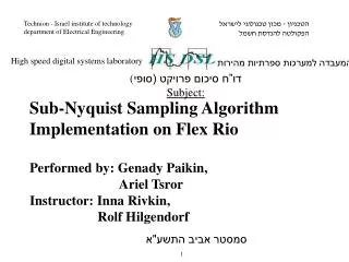
High Speed Digital Systems Lab Sub-Nyquist Sampling Algorithm Implementation on Flex RioMid Presentation Presenters: GenadyPaikin, Ariel Tsror. Supervisors : Inna Rivkin, Rolf Hilgendorf. Yearly Project Part A
Agenda : • Project overview • Goals • Hardware • Learning Process • Sampling stage • CTF module • DSP module • SCD module • Learning LabView • Adjusting Xlinx Chipscope to NI's FlexRio • DSP module Formation • Gantt Chart
Project Overview • The project is part of the Sub-Nyquist sampling and reconstruction card. • Our goal is to implement 2 units – CTF & DSP, on FlexRio FPGA cards under NI LabView environment. • The unit also includes the Xampling sampling card And the Expand unit.
Hardware : • NI chassis with 4* FlexRio FPGA modules • FlexRio : • Model : NI PXIe 7965R • Bus : PXI Express • FPGA : Virtex-5 SX95T (Xilinx) • FPGA memory : 8,784 Kbits • Onboard Memory : 512MB • FPGA Slices : 14,720 • FPGA DSP Slices : 640 • A/D. • Xampling sampling card. * Expand, DSP, CTF, Reconstruction
Learning Process : • Learning process composed of 2 independent processes : • Algorithm : • System main concept. • Sampling stage (Xampling and Expand). • CTF module. • DSP module (inc. SCD). • LabView : • LabView main concepts. • FPGA under LabView. • Integration. • Implementing Basic unit as training.
High Level Architecture : Xampling
NI Chassis Host PXIe Signal Generator FlexRio – Expand FlexRio – CTF FlexRio – DSP+SCD FlexRio – Analog Back-End LVDS 300 MB/s 4 X A/D MWC / Xamping
Sampling stage : • The sampling stage contain two units • Xampling sampling card. • Expand. 12X20.8 Mhz digital 4X62.5 Mhz digital Xampling A/D 62.5 Mhz (250 1:4 decim.) Expand 1:3 Analog in
CTF module : • Task : Detects the Support of x(t) and forward it to DSP unit. • Triggered at : • Initiation. • SCD interrupt. • The unit based on OMP (Orthogonal Matching Pursuit) algorithm.
Block Diagram : A A MP Supp y[n] frame calculation Q
DSP module : • Task: Reconstructs the signal from the samples. • The unit receives the samples from the memory (latency fifo), matrix A from the memory, and signal support from the CTF unit. • The support and samples are coordinated by the latency fifo. • The unit performs pseudo-inverse of matrix A (calculates As) using the signal support, that is received from the CTF. The inverse is done by QR Decomposition algorithm. • Finally the unit multiply the delayed signal with matrix As.
DSP module : DSP Matrix A (from memory) Pseudo Inverse As+ Signal support (from CTF) Reconstructed signal Signal’s sample (from memory) Multiplication
SCD module : • Task: Detects if there is a change of the signal support. • The unit uses the signal energy to decide if the CTF needs to recalculate the signal support. Recalculate support (to CTF) Signal’s sample (from expand) Support Change Detector
Learning LabView : • Basic level • We ran a simple application using LabView basic tools. • VHDL in LabView • We added a simple VHDL component using IP integration node. • We added a simple VHDL component using Component-Level IP (FPGA Module). • We used "host VI" to open "target VI“ • We used FPGA methods from the host.
Adjusting Xlinx Chipscope to NI's FlexRio: • We created chipscope component using Xilinx core generator (ILA, ICON). • We generated CLIP+xml file using CLIP node xml generator. • We defined chipscope component as CLIP node. • We connected manually JTAG cable to fit NI 5781 digital outputs/inputs (PFI).
Adjusting XlinxChipscope to NI's FlexRio: • We connected the chipscope component with the basic VHDL component that we had created earlier on FPGA target. • We connected the required outputs/inputs of the chipscope component with the PFIs.
Adjusting Xlinx Chipscope to NI's FlexRio: • Problems: • We tried to run whole things together, however the chipscope analyzer couldn't recognize the device. • There are no tutorials on this theme except the one we used, and it isn’t compatible with Xilinx or LabView versions that exist in the lab. • Ways to solve it: • We wait for official answer from NI.
Adjusting XlinxChipscope to NI's FlexRio: Target VI Implementation IP integration node Component Level IP (CLIP)
Adjusting XlinxChipscope to NI's FlexRio: Host VI Implementation
Multi-Clock Domain: • Creating example with different clock rates in the same design.
DSP module Formation: • Steps: • Learning previous implementation. • Coding blocks with VHDL. • Creating needed blocks in COREGEN. • Debugging blocks with Model Sim. • Importing VHDL components into LabView. • Assembling the whole module in LabView. • Debugging the module on the FPGA.