Download
1 / 26
260 likes | 449 Views
P09311 Interface for Multipurpose Driver/ Data Acquisition System. Team. Adam Van Fleet (EE) DAQ Hardware Development FPGA/DAQ Hardware Interface Development Project Leader David Howe (EE) DAQ Interfacing & USB Hardware Development FPGA/DAQ Hardware Interface Development

E N D
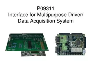
P09311Interface for Multipurpose Driver/ Data Acquisition System
Team • Adam Van Fleet (EE) • DAQ Hardware Development • FPGA/DAQ Hardware Interface Development • Project Leader • David Howe (EE) • DAQ Interfacing & USB Hardware Development • FPGA/DAQ Hardware Interface Development • Michael Doroski (CE) • DAQ Interface Development (software) • Custom FPGA logic • Thomas (TJ) Antonoff (CE) • USB interface development (software) • Andrew Weida (CE) • FPGA Bluetooth interface development (UART) • GUI Development and PC Serial Communication
Hardware-Level System Overview P08311 DAQ Board ASIC or Robotics Input Windows-Based PC DLP-USB245M USB Adapter 12-pin (up to 1MB/s xfer) 32-pin (500 kbps xfer) USB RS-232 RS-232 Parani ESD210SK Bluetooth Dev. Kit Digilent Spartan-3 Board
I/O 1 24 I/O 23 2 5 I/O 6 22 3 7 I/O 8 21 4 9 I/O 10 5 20 11 I/O 12 6 19 13 I/O 18 14 7 15 I/O 16 8 17 17 RD 9 18 16 19 WR 10 15 20 21 TXE 11 22 14 23 RXF 12 13 24 25 26 27 28 29 30 31 32 33 34 5 6 Pin-Outs for Additional Hardware 7 DLP-USB245M Pins 13-24 are connected to FPGA pins 7 through 18 of connector A1 First 30 pins from connector A2 Second 2 pins from connector A1
Top Level: USB & Bluetooth Architecture Design FPGA Dual-Input Buffer 8 Mbps USB FIFO USB Data Routing Logic USB Cable 500 kbps Dual-Input Buffer Dual-Output Buffer DAQ Custom Logic PC Dual-Output Buffer RS232 1.2 - 230 kbps Dual-Output Buffer UART Dual-Input Buffer Tx Tx Bluetooth Wireless Serial Rx Rx Bluetooth Modules
Data Path from DAQ to FPGA (Serial to Parallel Conversion)
Data Path from FPGA to DAQ (Parallel to Serial Conversion)
Custom Logic FSM State Diagrams FSM_In FSM_Out
Spartan-3 Starter Board – RS232 Interface • Hardware flow control is not supported on the connector. The port’s CD, DTR, and DSR signals connect together. Similarly, the port’s RTS and CTS signals connect together. • The Parani-ESD has configurable hardware flow control. When hardware flow control is not being used, the Parani-ESD clears the buffer to secure room for the next data when the buffer becomes full. Loss of data may occur. As the transmission data becomes large, the possibility of data loss becomes greater.
UART Transmit State Machine stop_tx tx_tick= 1 tx_bit_cnt = 1 Stop_bit: Keep TxBusy asserted When LD = ‘1’ Latch input data Tx_data -Shift out data bit by bit -Decrement tx_bit_cnt idle LD = ‘1’ load_tx_data tx_tick = 1 Put data in correct format: start+data bits
UART Receive State Machine RxBitCnt = 8 Here during stop bit Latch data to output RX_RDY = ‘1’ stop_rx edge_rx Should be near Rx _d edge Wait on start bit: - Synchronize with rx_tick - Sample RX at mid-bit and verify the Start bit rx_tick = 1 rx_tick = 1 start_rx shift_rx rx_tick = 1 Sample Data: -shift rx into a register -increment bit counter Rx_d = 1 Rx_d = 0 rx_tick = 1 Wait on Rx_d falling edge (start bit occurs) Framing error rx_ovf idle
PC Architecture Design (C#) PC Data Storage Format: <data>,timestamp; USB Cable Connection Handler using System.IO.Ports: SerialPort Class Data Data Serial Cable Control Signals Data Manager GUI Connection Handler Connection Media Connection Info
Appendix Spartan-3 Board Reference Material http://www.digilentinc.com/Products/Detail.cfm?Prod=S3BOARD&Nav1=Products&Nav2=Programmable DLP-USB245M USB Adapter http://www.dlpdesign.com/usb/usb245.shtml Parani ESD210SK Bluetooth Dev. Kit http://www.rfphone.com/files/ESD110.pdf