Download
1 / 27
270 likes | 285 Views
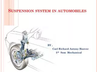
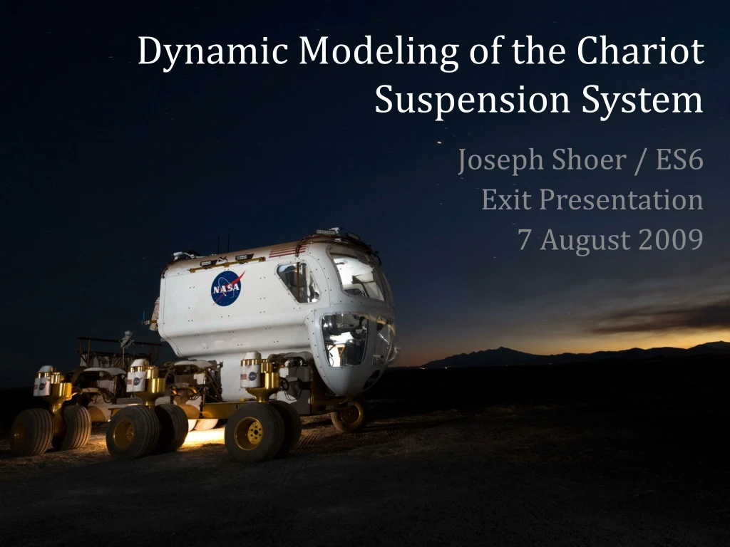
Dynamic Modeling of the Chariot Suspension System. Joseph Shoer / ES6 Exit Presentation 7 August 2009. Introduction. Personal Background. Introduction. Space Systems Research at Cornell. Magnetic Flux Pinning Autonomous docking Modular self-assembly Large-scale structures

E N D
Dynamic Modeling of the Chariot Suspension System Joseph Shoer / ES6 Exit Presentation 7 August 2009
Introduction Personal Background
Introduction Space Systems Research at Cornell • Magnetic Flux Pinning • Autonomous docking • Modular self-assembly • Large-scale structures • System reconfiguration www.SpacecraftResearch.com
Introduction Chariot Small Pressurized Rover (SPR)
Introduction Chariot Small Pressurized Rover (SPR) Chariot Rover Development • Planetary surface exploration requires mobility • SPR allows extended (days-weeks) traverses with high visibility and relatively easy ingress/egress • Traverse rugged planetary terrains to high science value targets • ES supports ER in Gen 1 concept analysis and Gen 2 vehicle development
Introduction Chariot Small Pressurized Rover (SPR) ES Rover Involvement • Stress, loads and design support prior to Gen 2 • Support Gen 1 Rover failure analyses • Support Gen 2 design recommendations • Develop FEM component models • Cabin pressure vessel • Develop rigid body model
Introduction Chariot Small Pressurized Rover (SPR) ES Rover Involvement • Stress, loads and design support prior to Gen 2 • Support Gen 1 Rover failure analyses • Support Gen 2 design recommendations • Develop FEM component models • Cabin pressure vessel • Develop rigid body model Focus on Suspension System
Introduction Objective Develop a dynamic model of the vehicle suspension to help understand dynamic loads on the suspension system in the operating environment. This will promote optimal vehicle design in Gen 2 development.
ADAMS Model ADAMS Model Components
ADAMS Model ADAMS Model Components Nonstructural masses Cabin 960 kg 1200 kg total Wheel modules 210 kg each Frame 210 kg Balance 740 kg CG 24 cm forward
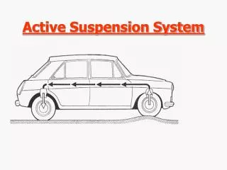
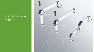
ADAMS Model Suspension System Dynamic Model
ADAMS Model Suspension System Dynamic Model
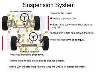
ADAMS Model Suspension System Dynamic Model Four-bar linkages Joints with 5DOF stiffness Spring Vehicle weight Ground
ADAMS Model Suspension System Dynamic Model Back Plate • Key component for loads • Previous failure analysis • FEM in development • (Photo: Leslie Schaschl/ES4)
ADAMS Model Suspension System Dynamic Model Passive spring/dampers • Stiffness: 600 lbf/in • Damping from data
ADAMS Model Suspension System Dynamic Model Screw Rail • Moves along ball screw • (Change spring endpoint) • Actuates suspension angle Motor Ball Screw
ADAMS Model Suspension System Dynamic Model Fixed joint • Wheel module / frame Crab angle Wheel drive motion • Constant speed rotation Tire-ground contact • Tire stiffness from data • Simple tire damping • Tire/ground friction
Capabilities Simulation Capabilities: Dynamic Behaviors
Capabilities Simulation Capabilities: Dynamic Behaviors
Capabilities Simulation Capabilities: Result Sets Extract Forces in Joints or Bodies Extract Torques in Joints or Bodies ADAMS can also extract stresses in flex bodies
Capabilities Simulation Capabilities: Active Suspension
The Future Model Fidelity Improvements • Improve nonstructural mass distribution • Improve tire/ground interaction model • (“Sinking” issue, ground and tire materials) • Improve active control implementation • (Sensor, motor dynamics; control law)
The Future Model Extension Possibilities • Implement additional control modes • (steering assist, climbing, etc) • Include FEM flexible bodies • (back plate, bushings, etc) • Add runtime wheel steering • (run test courses)
The Future Experimental Correlation • Add wireless instrumentation to vehicle • Characterize suspension accelerations • Input to model
Conclusions • ES6 now has a multibody dynamics model for the six-wheeled SPR • This model promises excellent possibilities for improvement and extension • This model can provide stress and load information under dynamic conditions, which will feed into optimization and development for the Gen 2 rover
Acknowledgments Alex Tovar Tim Rupp John Schliesing Ed Herrera Beverly Haygood Courtney Crooks Some images from EA Imagery Online library
Dynamic Modeling of the Chariot Suspension System Joseph Shoer / ES6 Exit Presentation 7 August 2009