Download
1 / 24
240 likes | 599 Views
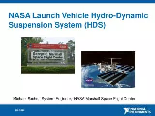
NASA Launch Vehicle Hydro-Dynamic Suspension System (HDS). Michael Sachs, System Engineer, NASA Marshall Space Flight Center. Agenda. History of the HDS and IVGVT HDS Refurbishment and D esign HDS Control Room HMI’s HDS System Architecture IEEE1588 PTP (GPS, UTC, TAI, DST)

E N D
NASA Launch Vehicle Hydro-Dynamic Suspension System (HDS) Michael Sachs, System Engineer, NASA Marshall Space Flight Center
Agenda History of the HDS and IVGVT HDS Refurbishment and Design HDS Control Room HMI’s HDS System Architecture IEEE1588 PTP (GPS, UTC, TAI, DST) cRIO SCADA Reference Design
What is a Hydrodynamic Suspension System (HDS)?Integral part of IVGVT allowing meas. of vehicle modal characteristicsVerification of FEM, improve GN&C stability, identify resonance anomalies 7,200,000 lb Lifting cap. 6 Axis DOF to simulate Free-Free boundary flight conditions. Strategically placed electro-dynamic shakers simulate thrust oscillation and acoustic shock.
Saturn V in the Test Stand, circa 1966 Two people pushing on the nose cone or the fins on the first stage, could deflect the vehicle as much as two inches. Prior to the HDS, IVGVT was accomplished by suspending the vehicle with cables. Prohibitive due to weight limitations and cable resonance.
Original HDS testing, circa 1965Martin Marietta Engineers I wonder what a day around hydraulic oil does to a white shirt and tie?
Refurbished HDS Cylinder and PistonHydrodynamic Suspension System One year to refurbish 4 HDS, replacement cost > $1,000,000
HDS Piston and CylinderHydraulic Lift with N2 Gas Spring HPU SVU Unique Design: Nearly 100% inefficient but 100% effective! Why? Continuous Hydraulic flow through and across bearing surfaces.
Hydraulic Pump Unit and Sump Valve StandHydrodynamic Suspension System Interface to wide variety of analog and digital controls and sensors Motor Controls (4), Discrete Valves (24), Proportional Valves (10), Pressure (20), Temp (9), Flow (3), Discrete Inputs (45), RTD (3), Discrete Outputs (14)
Design Goals: • Extensible Architecture supporting Distributed RT control • 2. Workbook based Configuration (GXML based) • 3. Instrumentation Management Tools • a. Tag Properties: Scaling, Filtering, ZOFS, Initial Value, DB% • b. Target Imaging • c. HMI bindings
Design Goals: • 24/7 Historical Data Logging (up to 20Hz) • RT Target sync to GPS, timestamped +/- 1ms • 6. Diagnostics • a. Multi-Tiered Alarm • b. RT process Monitor • c. Syslog, DSM • 7. Safety/Reliability features (FMEA driven)a. Watchdog based ESTOP->Park • b. Pump Dropout detection • c. N2 pressure interlocks • d. Bearing Contact monitor
HDS Instrumentation ManagerOne stop shopping for all your HDS configuration needs Overview of HDS networked devices, cRIO, HMI, PXI-6682
HPU HMI, Primary Operation Screen Pump Startup Sequencing, Tank Heater/Level, HE Temp Reg. +/- .2F, Filter Life Monitor
HDS HPU, Manual Pump Controls Touchpanel aware data entry, Tag ZOFS, Tag Stats Display
HDS HPU, Manual Pump Controls Touch Panel Numeric Data Keypad, activated by 2s touch on any control
HDS HPU, Manual Pump Controls HMI tag stats display, right click on any control or indicator
SVU HMI, Operate Screen Individual and sync’d HDS control, N2 Autocharge, DPH (Dynamic Piston Height Control) dPH/dt, DPH Mean, HDS state, Bearing Contact Monitor (transient and persistent)
HDS Software ArchitectureMVC (Model View Controller) Model – SVE/PSP interface supports NSV bindings, events, static/dynamic NSV access
cRIO 1588 TimeSync • IOV Timestamp by Module in Scan Engine • IOV -> NSV binding preserves timestamp • +/- 100us RT system time, +/- 1ms data timestamp PC cRIO Scan Engine NSV NSV IOV Data Timestamp Citadel Module TimeSync 1588 PTP Slave IEEE 1588 Ethernet GPS 1588 PTP Master TAI (1588) = GPS+19s UTC = TAI-34s PXI-6682
HDS Instrumentation ManagerWorkbook Configuration, Compile to GXML -> Target
DSM Historical Trend Capability Manual Shake Test, Natural HDS damping characteristic
DSM Historical Trend Capability New water chiller cycling disturbances
cRIO SCADA Reference Design Can be obtained at www.viScience.com Features: XLS/GXML Configuration Manager On-the-fly cRIOconfig. deployment Per channel SR, Filter, Scaling,DB, ZOFS HMI->cRIO Messaging (async and sync) Built-in TP Controls HMI Tag Management a. Creates NSV binding b. Creates embedded HMI Tag Desc. c. ZOFS apply/remove at tag Critical timing verification Syslog (UDP) CVT API