Download
1 / 20
200 likes | 460 Views
Explore the detailed functioning of a CPU, from cache storage to branch prediction, and learn about data manipulation methods like logical operations, shifts, and program execution. Discover the differences between CISC and RISC computing approaches.

E N D
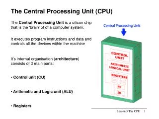
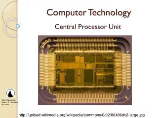
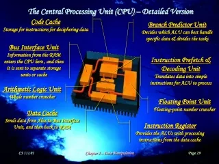
The Central Processing Unit (CPU) – Detailed Version Code Cache Storage for instructions for deciphering data Branch Predictor Unit Decides which ALU can best handle specific data & divides the tasks Bus Interface Unit Information from the RAM enters the CPU here , and then it is sent to separate storage units or cache Instruction Prefetch & Decoding Unit Translates data into simple instructions for ALU to process Arithmetic Logic Unit Whole number cruncher Floating Point Unit Floating-point number cruncher Data Cache Sends data from Alus to Bus Interface Unit, and then back to RAM Instruction Register Provides the ALUs with processing instructions from the data cache Chapter 2 – Data Manipulation
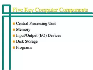
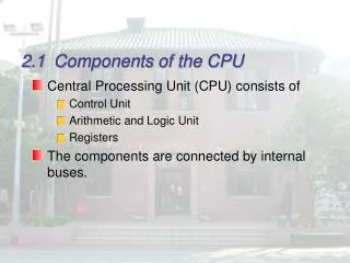
The Central Processing Unit (CPU) –Simplified Version CPU Registers Special memory cells to temporarily store the data being manipulated RAM Control Unit Circuitry to coordinate the operation of the computer ALU Circuitry that manipulates the data Bus Chapter 2 – Data Manipulation
The Machine Cycle DECODE instruction to determine what to do CONTROL UNIT ARITHMETIC/LOGIC UNIT EXECUTE the decoded instruction FETCH the next instruction from main memory STORE the result in main memory MAIN MEMORY Chapter 2 – Data Manipulation
Main Memory Cells : : Registers Control Unit 00 EE 01 EF 02 F0 0 03 F1 1 04 Program Counter (Keeps track of the address of the next instruction to be executed) F2 2 05 F3 3 06 F4 4 07 F5 5 08 F6 6 09 F7 7 0A F8 8 0B F9 9 Instruction Register (Contains a copy of the 2-byte instruction currently being executed) 0C FA A 0D FB B 0E FC C 0F FD D 10 FE E 11 FF F : : Sample Machine Architecture CPU ALU Bus Chapter 2 – Data Manipulation
Op-Code Field (specifies the operation to be performed) Operand Field (gives further details pertinent to the operation) Machine Instruction Format Sample Machine Language Chapter 2 – Data Manipulation
Sample Program 205C Load register 0 with the integer 92 (hexadecimal 5C) 300E Store the contents of register 0 at main memory address 0E 205A Load register 0 with the integer 90 (hexadecimal 5A) 300F Store the contents of register 0 at main memory address 0F 110E Load register 1 with the bit pattern at main memory address 0E 120F Load register 2 with the bit pattern at main memory address 0F 5012 Add the contents of registers 1 & 2 and put the sum in register 0 300D Store the contents of register 0 at memory address 0D C000 Halt execution In an advanced language, like C++, this program would be: void main() { int X, Y, Z; X = 92; Y = 90; Z = X + Y; } Chapter 2 – Data Manipulation
Logical Operations The following operations are easy to incorporate into circuitry and can form the building blocks of many more sophisticated operations… The AND Operation 1 AND 1 1 1 AND 0 0 0 AND 1 0 0 AND 0 0 10101001 AND 10011100 10001000 00001111 AND 10110101 00000101 The OR Operation 1 OR 1 1 1 OR 0 1 0 OR 1 1 0 OR 0 0 10101001 OR 10011100 10111101 00001111 OR 10110101 10111111 The Exclusive-OR (XOR) Operation 1 XOR 1 0 1 XOR 0 1 0 XOR 1 1 0 XOR 0 0 10101001 XOR 10011100 00110101 00001111 XOR 10110101 10111010 Chapter 2 – Data Manipulation
Shift Operations Shift operations are used to move bits within a memory register to facilitate decimal alignment in scientific notation and multiplication and division by powers of two… The Shift-Right Operation (i.e., Division by 2) Examples: Shift-Right(01001101) = 00100110 (i.e., Shift-Right(77) = 38) Shift-Right(10110011) = 11011001 (i.e., Shift-Right(-77) = -39) The Shift-Left Operation (i.e., Multiplication by 2) Examples: Shift-Left(00110101) = 01101010 (i.e., Shift-Right(53) = 106) Shift-Left(11001011) = 10010110 (i.e., Shift-Right(-53) = -106) Shift-Left(10010110) = 00101100 (i.e., Shift-Right(-106) = 44???) Chapter 2 – Data Manipulation
Another Sample Program This program examines two positive numbers, x and y, which are initially located at main memory addresses 3C and 3D. The program determines which integer is larger and places the result in main memory address 3E. The methodology involves computing –y (by complementing y and adding one), and then adding that to x to yield x-y. This is then examined to determine whether it is positive or negative, which decides which number was larger (i.e., y is larger if x-y is negative, while x is larger if x-y is positive). Chapter 2 – Data Manipulation
CISC vs. RISC • Complex Instruction Set Computers • Early computers were designed using the CISC approach: • Complicated set of instructions that perform sophisticated operations, often in more than one clock cycle • Very few memory registers on the CPU • It isn’t viable to “pipeline” operations • Reduced Instruction Set Computers • More recent computers use the RISC approach: • Much smaller instruction set, each performing a simple operation in a single clock cycle • Room on the chip for more registers, etc. • “Pipelining” of operations more viable Chapter 2 – Data Manipulation
Parallel Processing Traditional computers have a single processor. They execute one instruction at a time and can deal with only one piece of data at a time. These machines are said to have SISD (Single Instruction, Single Data) architectures. When multiple processors are applied within a single computer, parallel processing can take place. There are two basic approaches used in these “supercomputers”: • SIMD (Single Instruction, Multiple Data) Architectures • Each processor does the same thing at the same time to its own portion of the data • Example: Have the processors perform the graphics rendering for different sectors of the viewscreen: • MIMD (Multiple Instruction, Multiple Data) Architectures • At any given moment, each processor does its own task to its own portion of the data • Example: Have some processors retrieve data, some perform calculations, and some render the resulting images: Chapter 2 – Data Manipulation
Output Devices: CRT Display Monitors Cathode-ray tubes are the most common type of graphics monitor display: High-voltage interior coating Heating filament Cathode Control grid Phosphor coating Electron beam Focusing system Vertical deflection Horizontal deflection Chapter 2 – Data Manipulation
Shadow Mask Electron Guns Screen with RGB Phosphor Triads Output Devices: Shadow-Mask Color CRTs By associating three phosphors (red, green, and blue) with each screen pixel, and using three independent electron guns, an entire spectrum of colors is made possible: Chapter 2 – Data Manipulation
Output Devices: Liquid Crystal Displays For flat-panel displays (like those used on laptop computers), liquid crystals and polarized glass are used to determine the brightness of individual pixels: • When a charge is applied to a pixel’s liquid crystals, the crystals reorient themselves to prevent light from passing through the polarized glass in which the crystals are sandwiched. • Color filters are used to give each pixel a red, green, or blue color. • A triad of these pixels makes up a single-colored “super-pixel”. http://electronics.howstuffworks.com/lcd1.htm Chapter 2 – Data Manipulation
Input Devices: Keyboards One of the principal devices for providing input to a computer is the keyboard. When a key is pressed, a plunger on the bottom of the key pushes down against a rubber dome… …the center of which completes a circuit within the keyboard, resulting in the CPU being signaled regarding which key (or keys) has been pressed. Chapter 2 – Data Manipulation
Input Devices: Computer Mice Chapter 2 – Data Manipulation
information information time time Data Communication: Analog & Digital Data What is the difference between analog and digital data? Analog is a continuous display of information, making it “analogous” to the actual information. The process of recording, storing, displaying, or transmitting analog data is largely a mechanical process. Digital is a discrete display of information, using a sequence of values to approximate the actual information. The process of recording, storing, displaying, or transmitting digital data is largely a numerical process. Chapter 2 – Data Manipulation
Data Communication: Modems Digital data must be modulated into analog signals if it’s going to be transmitted across an analog medium (like most telephone lines). After transmission, it must be demodulated back into its original digital form. Cables between the workstation and the modem and between the modem and the telephone jack A dial-in pool of 96 modems: Six terminal servers, each connecting 16 modems to a network Chapter 2 – Data Manipulation
cos(ct) m1(t) X cos(ct) m1(t)+sin(ct) m2(t) m2(t) X sin(ct) 2cos(ct) m1(t) m1(t)+cos(2ct) m1(t) +sin(2ct) m2(t) FILTER OUT THE HIGH FREQUENCIES X cos(ct) m1(t)+sin(ct) m2(t) m2(t)+cos(2ct) m2(t) +sin(2ct) m1(t) X m2(t) 2sin(ct) Data Communication: Modulation & Demodulation Modulation of the digital signals m1 and m2 is effected at left via products with trig functions. Upon arrival, the message is demodulated below via trig multiplications, trig identities, and high-frequency filtering. Chapter 2 – Data Manipulation
1 2 3 4 5 6 7 8 9 10 11 12 13 14 15 16 17 18 19 20 21 22 23 24 25 Data Communication: Modem Interfaces • The EIA-232D connector connects a modem to a computer. • It uses a 25-pin connector, with each pin having a different meaning. • The meaning of each pin is activated by applying a voltage across it. Pin 20: Data Terminal Ready (i.e., “Hey! The computer’s ready to send something to the modem!” Chapter 2 – Data Manipulation