Submarine Evacuation System for Offshore Structures: Prototype Development
150 likes | 274 Views
This presentation focuses on the innovative prototype design of a deployable submarine evacuation system intended for offshore structures. Led by Dr. Michael Hinchey, the agenda covers key areas including project overview, prototype evolution, structural design, materials analysis, control mechanisms, and testing methods. The proposed solution aims to enhance safety in emergency situations, addressing the limitations of traditional lifeboats and freefall systems. Key goals include proving operational viability, identifying design requirements, and making recommendations for full-scale development.

Submarine Evacuation System for Offshore Structures: Prototype Development
E N D
Presentation Transcript
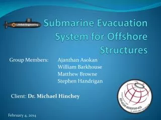
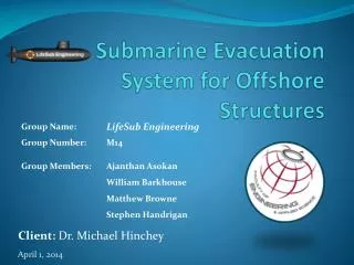
Submarine Evacuation System for Offshore Structures Client: Dr. Michael Hinchey
Agenda • Project Overview • Prototype Design Evolution • Structural • Material • Control • Analysis • Lifting • Finite Element Analysis (FEA) • Motion (Flow3D) • Control Codes & Sequence • Testing Methods • Deployment Strategies • Moving Forward • Questions
Project Overview • Current Problem • Lifeboats – Exposed to Hazards • Freefall – Uncontrolled • Proposed Solution • Deployable Submarine • Project Goals • Develop and Test Automated Submarine Prototype • Develop and Test Deployment Options • Identify Design Requirements • Prove Operational Viability • Make Recommendations on Full-scale Development
Prototype Design Evolution • Structural • Lifting Hook • Tail Sweep • Propeller Shroud • Material • Previous – 6” OD Aluminum Round Stock • Current • Hull – 6” ID, PVC Pipe • Endcaps – Solid Round Stock ABS • Shroud – RP ABS Phase 1 Phase 2
Prototype Design Evolution • Controls • Experimental Circuit (Breadboard) • Initial code testing • Printed Circuit Board (PCB) • Fine-tuning with prototype equipment • Execute submarine control
Analysis: Lifting • Applied Load: 125 (N) • Maximum Lift Acceleration: 1 (m/s2) • Lifting Hook – ¼” x 20 UNC Nylon • Maximum Stress due to Bending • Lifting Angle Limit: 10° (S.F. 2) • Torque Requirement: 1 (N-m) • End Cap Fasteners - 4 x ¼ x 28 UNC Nylon • Utilization: 2% of Yield Strength • Torque Requirement: 1 (N-m) 10°
Finite Element Analysis (FEA) • Quarter Model Hydrostatic Analysis • Boundary Conditions • Roller Side Boundaries • Fixed at Nose • Setup • Pressure: 60 kPa (~6m) • Mesh: 6mm curvature • Results • Limiting Safety Factor: 11.47 • Max Deflection: 35.2 µm MIN: 11.47 S.F.
Motion Analysis: Flow3D • Conditions • Preset amount of ballast • Fully submerged • Still water • Exclude buoyancy control • Uniform density • Setup • Acceleration: 0.1 m/s2 downwards • Disp. Mass: 11.2 kg; Mass: 11.31 kg • Hollow body with point mass • Result: COG ~10mm below COB 4 ft 5.2 ft 2.8 ft
Control Codes • Speed Control Code • Varying thruster RPM • Depth Control Code • Maintain desired depth band • Roll & Pitch Code • Continual monitoring of roll and pitch • Potentiometer • Replicates sensor • Thruster • Replicates thruster • ± 2.5 V • Stepper Motor • Replicates Pump • Ballast Control
Code Sequence + Φ - Φ + θ - θ Z1 + Z Z2
Testing Methods • Static Commissioning • Water Tight Hull Test • External Ballast System Pressure Test • Dynamic Commissioning • Depth Driven Ballast Test • Rotation Driven Thrust Test • Pitch • Roll • Depth
Deployment Strategies 1. Vertical Deployment • Propeller-down launch • Underwater • Avoid GBS interference 2. Horizontal Launch • Release bay filled with water • Exit from enclosed piping 3. Horizontal Docking • Connect with GBS 2. 1. 3.
Moving Forward • Refine Flow3D Model using an upgraded version of Flow3D • Complete construction and fabrication • Continue optimizing control codes • Perform testing and analysis • Phase 3 Decision: • Develop general recommendations for full-scale implementation
Questions? Thank-you www.lifesubengineering.weebly.com